Previous Next

OVERHAUL

1990–94 Vehicles
  1. Remove the strut from the vehicle.
  2. Remove the dust cover from the top of the strut.

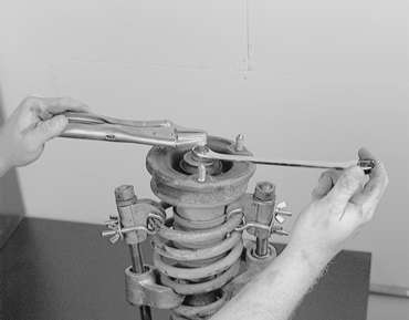
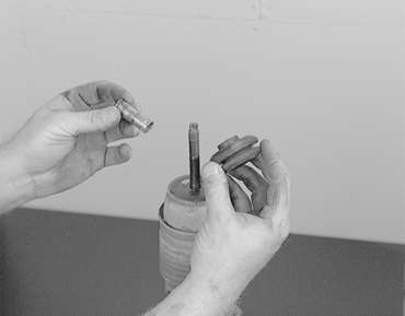
    NOTE: The self-locking nut should only be loosened. Do not remove the nut.

  3. While holding the spring upper seat with retainer tool CT–1112 or equivalent, loosen the self-locking nut.

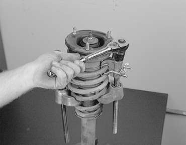
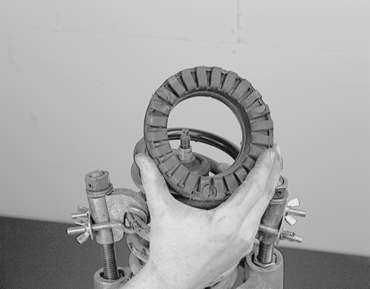
    Fig. 1: Spring seat holder tool used to disassemble 1990–94 strut assemblies

    Fig. 2: Hold the upper seat with the special tool . . .

    Fig. 3: . . . then loosen, but do not remove, the self-locking nut

  4. Place the strut assembly in a soft-jawed vise, then carefully compress the coil spring using spring compressor tool C–4838 or equivalent. Install the compressor tools so they are of equal distance apart. Tighten the compressor tools slowly and evenly. Do not use air tools on the spring compressors.

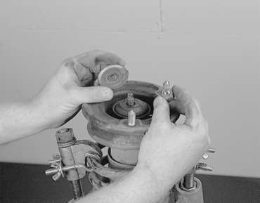
    Fig. 4: Use EXTREME care when compressing the coil spring

    Fig. 5: Exploded view of the front strut assembly

  5. Once the spring is compressed, remove the locknut.
  6. Remove the strut insulator, spring seat spring pad, bumper rubber and dust cover. Remove the coil spring.
  7. Inspect all parts for rust, damage or corrosion and replace as required.

    To assemble:

  8. Install the spring onto the strut assembly.
  9. Join the dust cover and the bump rubber and install onto the strut.
  10. Assembly the spring upper seat tot he piston rod, fitting the notch in the rod to the shaped hole in the spring seat. Line up the holes in the strut assembly spring lower seat with the hole in the spring upper seat. This is made easier using a long piece of stock to act as a guide.

    Fig. 6: Fit notch in the strut rod to the shaped hole in the spring seat

  11. Install the strut insulator.
  12. Install the self-locking nut. With the coil spring held compressed, provisionally tighten the self-locking nut. Correctly align both ends of the coil spring with the grooves in the spring seat, and loosen the spring compressor tool.

    Fig. 7: Installing the self-locking nut

  13. While holding the spring upper seat with tool CT–1112 or equivalent, tighten the new locknut to 43–51 ft. lbs. (60–70 Nm).
  14. Apply multi-purpose grease to the bearing part of the strut and insulator.

    NOTE: When applying grease to the strut and insulator, make sure the grease does not adhere to the rubber portion of the insulator.

  15. Install the dust cover onto the strut. Install the strut onto the vehicle.
1995–98 Vehicles

Fig. 8: Exploded view of the shock absorber and spring assembly

  1. Remove the shock and strut assembly from the vehicle.

    CAUTION
    Do not use air tools to tighten the compressor tool bolt.

  2. Use the proper spring compressing tools (MB991237 and MB991239) to compress the coil spring. Make sure to install the tools evenly so the maximum length will be attained within the installation range.

    Fig. 9: Assemble the proper compressor tools on the spring, then compress with a ratchet or wrench. Do not use air tools!

  3. While holding the piston rod, remove the self-locking nut.

    Fig. 10: Hold the piston rod with a pair of locking pliers, then remove the self-locking nut

  4. Remove the washer.

    Fig. 11: Remove the self-locking nut and washer

  5. Remove the upper bushing A, the upper bracket assembly and the upper spring pad.

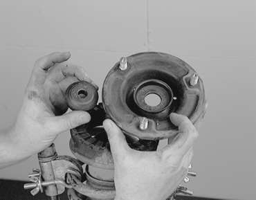
    Fig. 12: Remove the upper bushing and bracket assemblies

    Fig. 13: Lift off the upper spring pad

  6. Remove the collar, upper bushing B, cup assembly, rubber bumper and dust cover.

    Fig. 14: Remove the collar and the other bushing

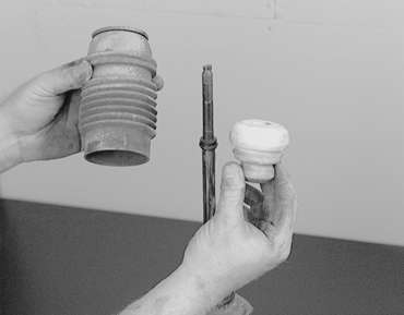
    Fig. 15: Remove the rubber bumper and dust cover

  7. Separate the coil spring and shock absorber assemblies.

    To assemble:

  8. Use the compressor tools to compress the coil spring, then install it to the shock absorber. Align the edge of the coil spring to the stepped portion of the shock absorber spring seat.

    Fig. 16: Make sure to align the coil spring with the stepped part of the shock spring seat

  9. Install the dust cover, rubber bumper, cup, upper bushing B, collar and upper spring pad.
  10. Install the upper bracket assembly, installing it so the position of the three bolts are in the proper orientation with the damper fork, as shown in the accompanying figure.

    Fig. 17: Make sure the upper bracket bolts are in proper position with the damper fork

  11. Install the other upper bushing.
  12. Install the washer and the self-locking nut. Temporarily tighten the self-locking nut, then remove the spring compressor tools and tighten the nut to 14–18 ft. lbs. (20–25 Nm) using a torque wrench. Do not use air tools to tighten the self-locking nut!
  13. Install the shock absorber assembly in the vehicle.

Previous Next