Previous Next

Lower Control Arm

REMOVAL & INSTALLATION

1990–94 Vehicles
  1. Disconnect the negative battery cable.
  2. Raise the vehicle and support safely.
  3. Remove sway bar links or mounting nuts and bolts from lower control arm. Remove the joint cups and bushings, if equipped.
  4. Disconnect the ball joint stud from the steering knuckle.

    Fig. 1: Use a suitable puller (MB990635 or equivalent) to separate the lower control arm ball joint from the knuckle using

  5. Remove the inner lower arm mounting bolts and nut.
  6. Remove the rear mount bolts. Remove the rear retainer clamp if equipped.
  7. Remove the arm from the vehicle.
  8. Remove the rear rod bushing, if service is required.

    Fig. 2: Exploded view lower control arm — 1990–94 models equipped with rubber bushing type stabilizer

    Fig. 3: Exploded view of the lower control arm — 1990–94 models equipped with pillow-ball type stabilizer

    To install:

  9. Assemble the control arm and bushing. Install the control arm to the vehicle and install the inner mounting bolts. Install new nut and snug temporarily.
  10. Install the rear mount clamp, bolts and replacement nuts. Tighten the clamp mounting nuts to 34 ft. lbs. (47 Nm). Temporarily tighten the clamp mounting bolt. Once the weight of the vehicle is on the suspension, the bolt will be tightened to 72 ft. lbs. (100 Nm).
  11. Connect the ball joint stud to the knuckle. Install a new nut and torque to 43–52 ft. lbs. (60–72 Nm).
  12. Install the sway bar and links.
  13. Lower the vehicle to the floor for the final tightening of the inner frame mount bolt.
  14. Once the full weight of the vehicle is on the suspension, tighten the inner lower arm mounting bolt nuts to 87 ft. lbs. (120 Nm). Tighten the inner clamp mounting bolt to 72 ft. lbs. (100 Nm).
  15. Inspect all suspension bolts, making sure they all have been fully tightened.
  16. Connect the negative battery cable.
1995–98 Vehicles

Fig. 4: Exploded view of the compression and lateral lower control arm assemblies

COMPRESSION LOWER CONTROL ARM
  1. Raise and safely support the vehicle.
  2. Remove the front wheel and tire assembly.
  3. Use the proper tool and disconnect the compression lower arm ball joint from the steering knuckle.

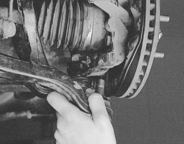
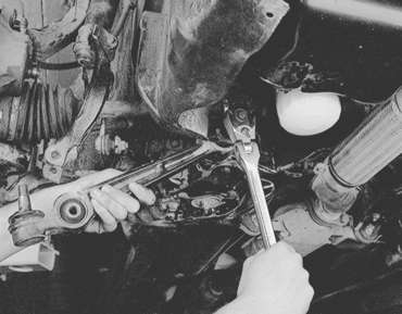
    Fig. 5: Separate the compression lower ball joint from the knuckle

  4. Remove the two mounting bolts and remove the compression lower arm.

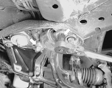
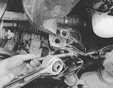
    Fig. 6: Unfasten the two compression lower control arm (see arrows)

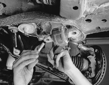
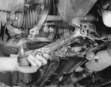
    Fig. 7: Remove the remaining mounting bolt . . .

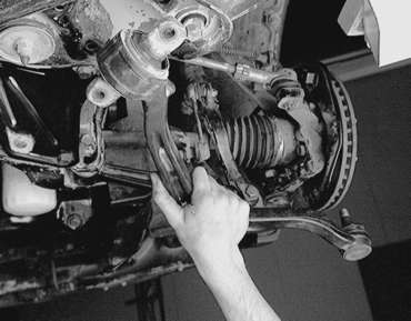
    Fig. 8: . . . then remove the compression lower control arm from the vehicle

    To install:

  5. Install the compression lower arm. Tighten the two mounting bolts to 60 ft. lbs. (81 Nm).
  6. Using a new self-locking nut, connect the ball joint to the knuckle assembly. Tighten the nut to 43–51 ft. lbs. (59–71 Nm).
  7. Install the wheel assembly and safely lower the vehicle to the floor.
  8. Check and adjust the front wheel alignment if necessary.
LATERAL LOWER ARM
  1. Raise and safely support the vehicle.
  2. Remove the wheel assembly.
  3. Remove the stay (bracket).
  4. Remove the shock absorber lower mounting bolt.
  5. Use the proper puller tool and disconnect the lateral lower arm from the knuckle assembly.
  6. Remove the lateral lower arm mounting bolt and the lateral arm.

    Fig. 9: After separating the later lower ball joint from the knuckle, unfasten the mounting bolt . . .

    Fig. 10: . . . then remove the mounting bolt and pull the lateral lower control arm from the vehicle

    To install:

  7. Install the lateral lower arm and temporarily install the mounting bolt. Do not tighten the bolt until the vehicle is on the floor at normal riding height.

    Fig. 11: To install, position the lateral lower arm in the vehicle, then install the mounting bolt hand-tight

  8. Use a new self-locking nut and connect the ball joint to the knuckle assembly. Tighten the self-locking nut to 43–51 ft. lbs. (59–71 Nm).
  9. Install the shock absorber lower mounting bolt, secure with the nut and torque to 64 ft. lbs. (88 Nm).
  10. Install the stay with the bolts and tighten them to 51–58 ft. lbs. (69–78 Nm).
  11. Install the wheel assembly and lower the vehicle to the floor.
  12. Tighten the lateral lower arm through-bolt and nut to 71–85 ft. lbs. (98–118 Nm).
  13. Check and adjust the front wheel alignment if necessary.

Previous Next