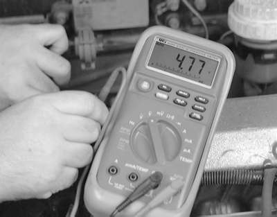
| Fig. 1: Testing the SIG circuit to the TP sensor
|
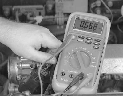
| Fig. 2: Testing the SIG RTN circuit of the TP sensor
|
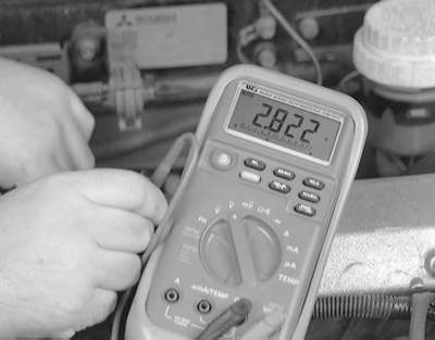
| Fig. 3: Testing the operation of the potentiometer inside
the TP sensor while slowly opening the throttle
|
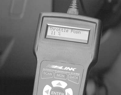
| Fig. 4: The TP sensor can be monitored with an appropriate
and Data-stream capable scan tool
|