These vehicles use several different types of joints. Engine size, transaxle
type, whether the joint is an inboard or outboard joint, even which side of
the vehicle is being serviced could make a difference in joint type. Be sure
to properly identify the joint before attempting joint or boot replacement.
Look for identification numbers at the large end of the boots and/or on the
end of the metal retainer bands.
The 3 types of joints used are the Birfield Joint, (B.J.), the Tripod Joint
(T.J.) and the Double Offset Joint (D.O.J.).
NOTE: Do not disassemble a Birfield joint. Service with a new
joint or clean and repack using a new boot kit.
The distance between the large and small boot bands is important and should
be checked prior to and after boot service. This is so the boot will not be
installed either too loose or too tight, which could cause early wear and cracking,
allowing the grease to get out and water and dirt in, leading to early joint
failure.
NOTE: The driveshaft joints use special grease; do not add
any grease other than that supplied with the kit.
The Double Offset Joint (D.O.J.) is bigger than other joints and, in these
applications, is normally used as an inboard joint.
- Remove the halfshaft from the vehicle.
- Side cutter pliers can be used to cut the metal retaining bands. Remove
the boot from the joint outer race.
- Locate and remove the large circlip at the base of the joint. Remove the
outer race (the body of the joint).
- Remove the small snapring and take off the inner race, cage and balls as
an assembly. Clean the inner race, cage and balls without disassembling.
- If the boot is to be reused, wipe the grease from the splines and wrap the
splines in vinyl tape before sliding the boot from the shaft.
- Remove the inner (D.O.J.) boot from the shaft. If the outer (B.J.) boot
is to be replaced, remove the boot retainer rings and slide the boot down
and off of the shaft at this time.
To install:
- Be sure to tape the shaft splines before installing the boots. Fill the
inside of the boot with the specified grease. Often the grease supplied in
the replacement parts kit is meant to be divided in half, with half being
used to lubricate the joint and half being used inside the boot.
- Install the cage onto the halfshaft so the small diameter side of the cage
is installed first. With a brass drift pin, tap lightly and evenly around
the inner race to install the race until it comes into contact with the rib
of the shaft. Apply the specified grease to the inner race and cage and fit
them together. Insert the balls into the cage.
- Install the outer race (the body of the joint) after filling with the specified
grease. The outer race should be filled with this grease.
- Tighten the boot bands securely. Make sure the distance between the boot
bands is correct.
- Install the halfshaft to the vehicle.
- Disconnect the negative battery cable. Remove the halfshaft.
- Use side cutter pliers to remove the metal retaining bands from the boot(s)
that will be removed. Slide the boot from the T.J. case.
- Remove the snapring and the tripod joint spider assembly from the halfshaft.
Do not disassemble the spider and use care in handling.
- If the boot is be reused, wrap vinyl tape around the spline part of the
shaft so the boot(s) will not be damaged when removed. Remove the dynamic
damper, if used, and the boots from the shaft.
To install:
- Double check that the correct replacement parts are being installed. Wrap
vinyl tape around the splines to protect the boot and install the boots and
damper, if used, in the correct order.
- Install the joint spider assembly to the shaft and install the snapring.
- Fill the inside of the boot with the specified grease. Often the grease
supplied in the replacement parts kit is meant to be divided in half, with
half being used to lubricate the joint and half being used inside the boot.
Keep grease off the rubber part of the dynamic damper (if used).
- Secure the boot bands with the halfshaft in a horizontal position. Make
sure distance between boot bands is correct.
- Install the halfshaft to the vehicle and reconnect the negative battery
cable.
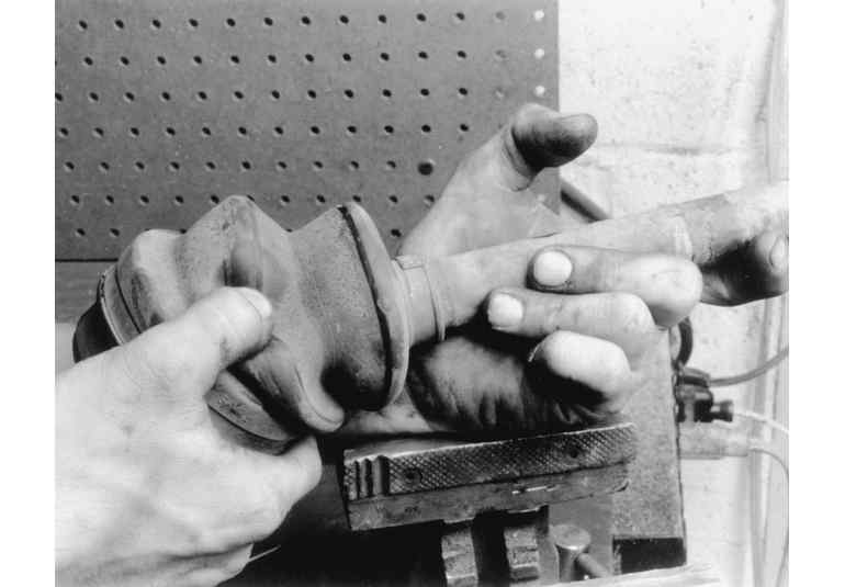
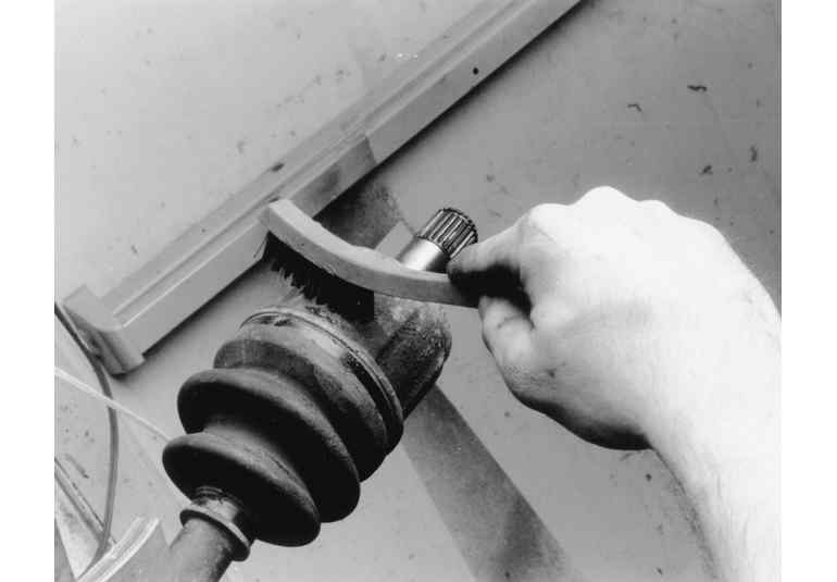
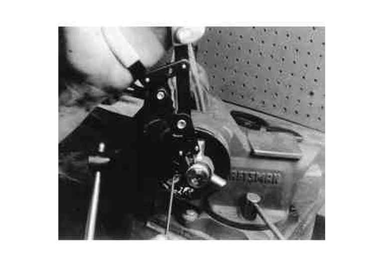
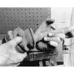
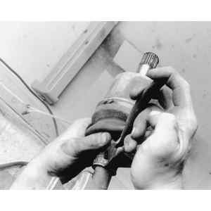
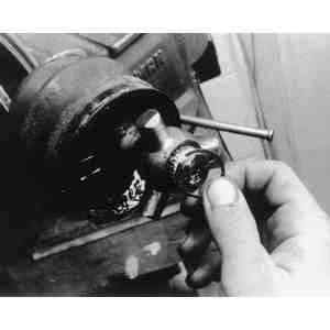
| Fig. 1: Check the CV-boot for wear
|
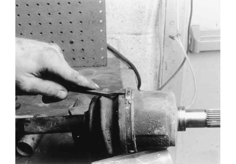
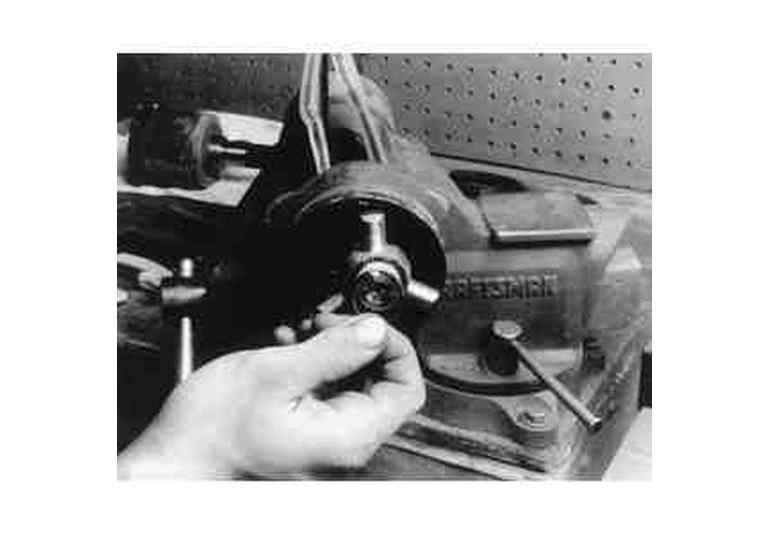
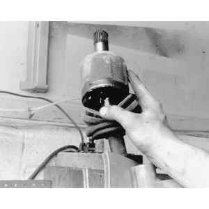
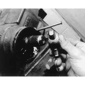
| Fig. 2: Removing the outer band from the CV-boot
|
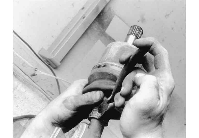
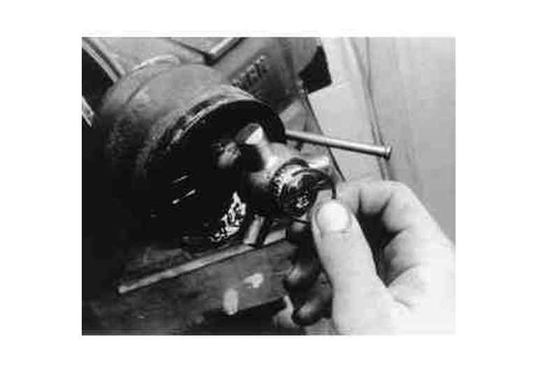
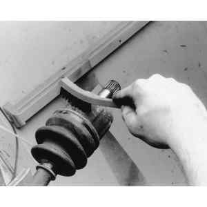
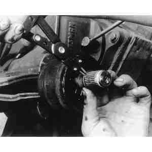
| Fig. 3: Removing the inner band from the CV-boot
|
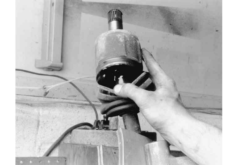
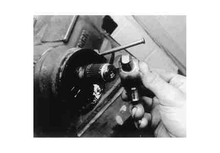
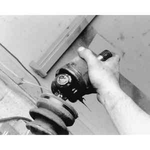
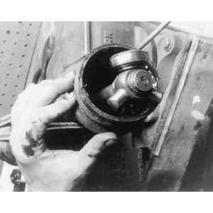
| Fig. 4: Removing the CV-boot from the joint housing
|
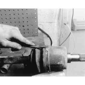
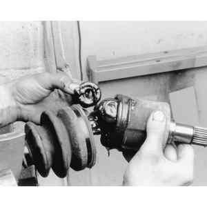
| Fig. 5: Clean the CV-joint housing prior to removing
boot
|
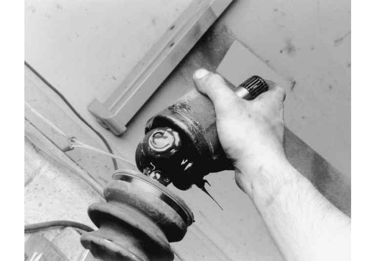
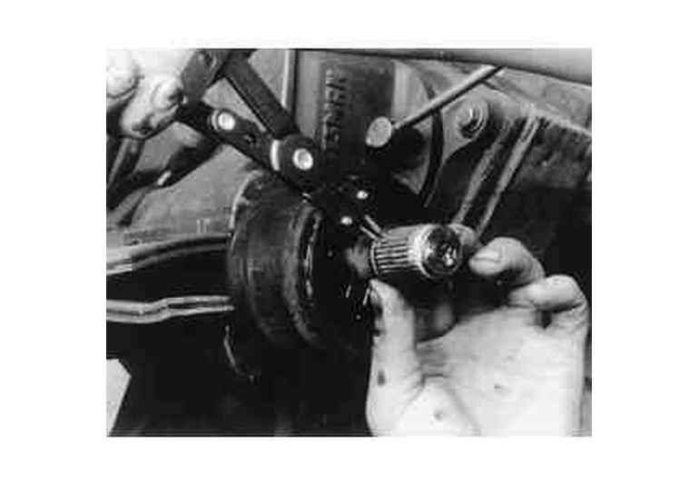
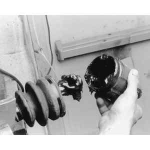
| Fig. 6: Removing the CV-joint housing assembly
|
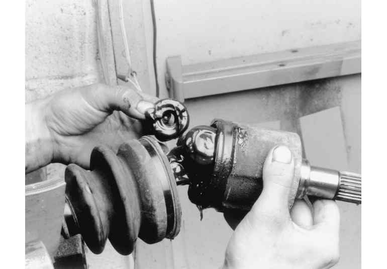
| Fig. 7: Removing the CV-joint
|
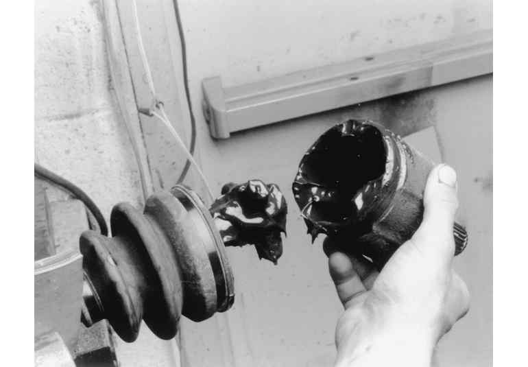
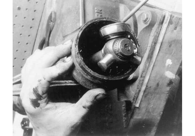
| Fig. 8: Inspecting the CV-joint housing
|
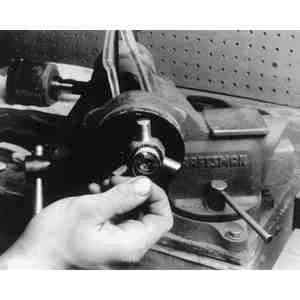
| Fig. 9: Removing the CV-joint outer snapring
|
| Fig. 10: Checking the CV-joint snapring for wear
|
| Fig. 11: CV-joint snapring (typical)
|
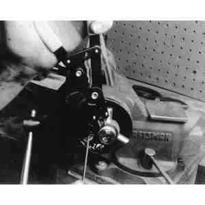
| Fig. 12: Removing the CV-joint assembly
|
| Fig. 13: Removing the CV-joint inner snapring
|
| Fig. 14: Installing the CV-joint assembly (typical)
|