Previous Next

Halfshafts

REMOVAL & INSTALLATION

Remove the cotter pin from the axle shaft . . .

. . . then loosen the axle nut while the vehicle is still on the ground

Use a suitable wrench to loosen . . .

. . . the nuts from the lower ball joint-to-steering knuckle junctions

Remove the lower coil-over shock lower mounting bolt and nut from the control arm

Use a suitable prytool to separate . . .

. . . the lower ball joints from the steering knuckle

Use a suitable prytool to release the inner CV-joint retaining ring from the transaxle by gently prying outward

Remove the inner joint from the transaxle until the spline completely clears the transaxle

Using a suitable punch and hammer, gently tap the halfshaft out of the steering knuckle . . .

. . . then slide the halfshaft out of the knuckle

Remove the halfshaft from the vehicle

Always replace the circlip on the inner joint before installing the shaft into the transaxle

  1. While the vehicle is still on the ground, remove the cotter pin, and loosen the axle nut.
  2. Raise the vehicle and support it safely.
  3. If equipped with ABS, remove the front wheel speed sensor.
  4. If equipped with Active Electronic Control Suspension (Active-ECS), perform the following:
    1. Loosen the nut that secures the air line to the to the top of the strut and discard the O-ring.
    2. Remove the bolts that secure the actuator to the top of the strut and remove the component. Disconnect the wiring harness.
  5. Disconnect the lower ball joint and the tie rod end from the steering knuckle.
  6. Remove the axle nut and the washer.
  7. If removing the left side axle with an inner shaft, remove the center support bearing bracket bolts and washers. Then, remove the halfshaft by setting up a puller on the outside wheel hub and pushing the halfshaft from the front hub. Tap the shaft union at the joint case with a plastic hammer to remove the halfshaft and inner shaft from the transaxle.
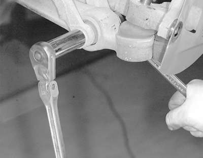
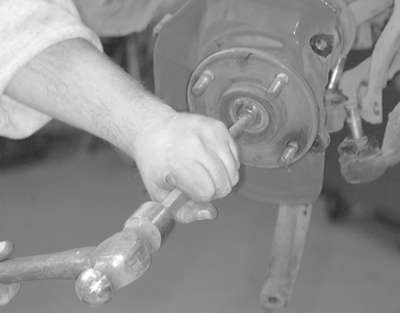
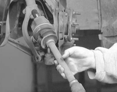
  8. If removing right side axle shafts without an inner shaft, remove the halfshaft by setting up a puller on the outside wheel hub and pushing the halfshaft 
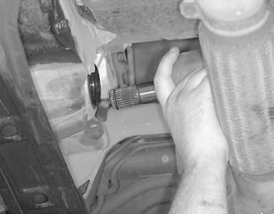
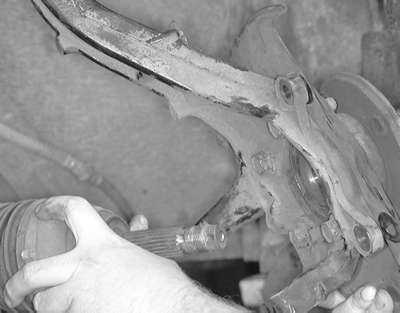
from the front hub. After pressing the outer shaft, insert a prybar between the transaxle case and the halfshaft and pry the shaft from the transaxle.

    NOTE: Do not pull on the shaft; doing so damages the inboard joint.

    To install:

  9. Replace the circlips on the ends of the halfshafts.
  10. Insert the halfshaft into the transaxle. Be sure it is fully seated.
  11. Pull the strut assembly out and install the other end to the hub.
  12. Install the center bearing bracket bolts and tighten to 33 ft. lbs. (45 Nm).
  13. Install the washer on the axle shaft so the chamfered edge faces outward. Install the axle nut, but do not tighten it fully at this time.
  14. Connect the ball joint to the steering knuckle. Torque the new retaining nut to 43–52 ft. lbs. (60–72 Nm) and secure with a new cotter pin.
  15. Connect the tie rod end to the steering knuckle. Torque the retaining nut to 21 ft. lbs. (29 Nm) and secure with a new cotter pin.
  16. If equipped with ABS, install the front wheel speed sensor.
  17. If equipped with Active-ECS, perform the following:
    1. Install the air line with a new O-ring.
    2. Install the actuator to the top of the strut. Connect the wiring harness.
  18. Install the wheel and lower the vehicle to the floor.
  19. Tighten the axle nut to 145–188 ft. lbs. (200–260 Nm) and secure with a new cotter pin.

Previous Next