

- Disconnect the negative battery cable.
- Raise the vehicle and support safely.
- Remove sway bar links or mounting nuts and bolts from lower control arm.
Remove the joint cups and bushings, if equipped.
- Disconnect the ball joint stud from the steering knuckle, using tool MB990635
or equivalent.
NOTE: It is important to use proper method when separating
joints. Damage to joint could occur, resulting in possible failure.
- Remove the inner lower arm mounting bolts and nut.
- Remove the rear mount bolts. Remove the rear retainer clamp if equipped.
- Remove the arm from the vehicle.
- Remove the rear rod bushing, if service is required.
To install:
- Assemble the control arm and bushing. Install the control arm to the vehicle
and install the inner mounting bolts. Install new nut and snug temporarily.
- Install the rear mount clamp, bolts and replacement nuts. Tighten the clamp
mounting nuts to 34 ft. lbs. (47 Nm). Temporarily tighten the clamp mounting
bolt. Once the weight of the vehicle is on the suspension, the bolt will be
tightened to 72 ft. lbs. (100 Nm).
- Connect the ball joint stud to the knuckle. Install a new nut and tighten
to 43–52 ft. lbs. (60–72 Nm).
- Install the sway bar and links.
- Lower the vehicle to the floor for the final torquing of the inner frame
mount bolt.
- Once the full weight of the vehicle is on the suspension, tighten the inner
lower arm mounting bolt nuts to 87 ft. lbs. (120 Nm). Tighten the inner clamp
mounting bolt to 72 ft. lbs. (100 Nm).
- Inspect all suspension bolts, making sure they all have been fully tightened.
- Connect the negative battery cable.
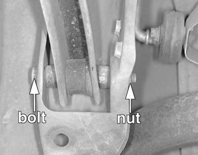
| Fig. 1: Remove the through-bolt connecting the knuckle
assembly to the lower control arm
|
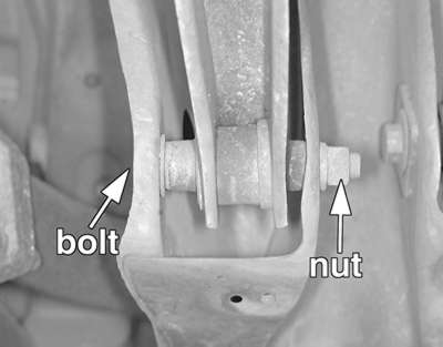
| Fig. 2: Remove the mounting bolt connecting the lower
control arm to the suspension crossmember
|
- Raise and support the vehicle safely.
- Remove the appropriate wheel assembly.
- If equipped with ABS, disconnect the speed sensor harness brackets from
the lower control arm.
- Disconnect the stabilizer bar link from the lower control arm.
- Remove the through-bolt, connecting the knuckle assembly to the lower control
arm.
- Remove the mounting bolt connecting the lower control arm to the suspension
crossmember.
- Remove the lower control arm from the vehicle.
To install:
NOTE: The control arm mounting bolts must not be fully
tightened until the full weight of the vehicle is on the ground.
- Install the control arm to the suspension crossmember and temporarily tighten
the mounting bolt.
- Connect the knuckle to the lower control arm and lightly tighten the through-bolt.
- Connect the stabilizer bar link to the control arm and tighten the nut to
28 ft. lbs. (39 Nm).
- Install the wheels and lower the vehicle to the floor.
- Once the full weight of the vehicle is on the suspension, tighten the lower
arm mounting bolt nuts to 71 ft. lbs. (98 Nm).
- Check rear wheel alignment and adjust if necessary.
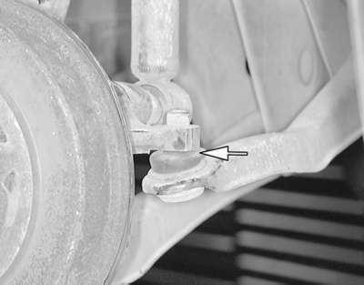
| Fig. 3: Disconnect the ball joint stud from the steering
knuckle
|
| Fig. 4: Remove the mounting bolt connecting the toe lower
control arm to the suspension crossmember
|
The lower ball joint is integral with the lower toe control arm. They are removed
and replaced as an assembly.
- Raise and support the vehicle safely.
- Remove the appropriate wheel assembly.
- Matchmark the control arm adjusting bolt to aid in reassembly.
- Using joint separator MB991113, disconnect the ball joint stud from the
steering knuckle.
- Remove the mounting bolts connecting the lower control arm to the suspension
crossmember.
To install:
- Connect the control arm to the suspension crossmember. Align the matchmarks
on the adjustment bolt and lightly tighten the bolt.
- Connect the ball joint stud to the knuckle and tighten the nut to 20 ft.
lbs. (28 Nm).
- Install the wheels and lower the vehicle to the floor.
- With the full weight of the vehicle on the ground, tighten the control arm
through-bolt to 50–56 ft. lbs. (69–78 Nm).
- Check rear wheel alignment and adjust if necessary.
- Raise and properly support vehicle. Remove appropriate wheel assembly.
- Matchmark the camber adjusting bolt to aid in reassembly.
- On vehicles equipped with Active Suspension, disconnect the ECS height sensor
rod from lower arm.
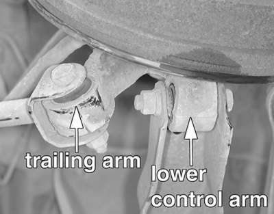
- Support trailing arm assembly and remove the self-locking nut connecting
the lower arm to the trailing arm.
- Disconnect the lower arm at the rear subframe. Remove the arm assembly.
To install
- Connect the control arm to the rear crossmember. Align matchmarks and lightly
tighten.
- Connect the control arm to the trailing arm and tighten the self-locking
nut to 54–61 ft. lbs. (75–89 Nm).
- Connect the ECS height sensor rod to the lower arm, if equipped.
- Install wheel and lower vehicle.
- With the full weight of the vehicle on the ground, tighten the control arm
to rear crossmember bolt to 54–61 ft. lbs. (75–89 Nm).
- Check rear wheel alignment and adjust if necessary.