NOTE: Prior to removal of the steering gear box, center the
front wheels and remove the ignition key. Failure to do so may damage the
SRS clock spring and render SRS system inoperative.
- Disconnect the negative battery cable.
- Disconnect the front exhaust pipe.
- If equipped with AWD, remove the transfer case assembly.
- Remove the bolt holding the lower steering column joint to the rack and
pinion input shaft.
- Remove the cotter pins and disconnect the tie rod ends.
- Remove the left and right frame members.
- Remove the stabilizer bar bracket.
- If equipped with four-wheel steering, disconnect the lines going to the
rear pump.
- Remove the rack and pinion steering assembly and its rubber mounts. Move
the rack to the right to remove it from the crossmember.
To install:
- Install the rack and mounting bolts. Tighten the bolts to 51 ft. lbs.
(70 Nm). When installing the rubber rack mounts, align the projection of
the mounting rubber with the indentation in the crossmember. Install the
pinch bolt.
- Connect the pressure and return lines to the rack and to the rear pump,
if equipped.
- Install the frame members and tighten the bolts to 43–51 ft. lbs.
(60–70 Nm).
- Connect the tie rods and install new cotter pins.
- Install the transfer case and front exhaust pipe.
- Refill the reservoir and bleed the system.
- Have a front end alignment performed.
- Disconnect the negative battery cable.
- Raise the vehicle and support safely.
- Drain the power steering fluid.
- Remove the main muffler assembly.
- Remove the rear shock absorber lower mounting bolts.
- Using the proper equipment, support the weight of the rear differential.
Remove the 2 small crossmember brackets.
- Remove the large self-locking crossmember mounting nuts on the differential
side.
- Remove the oil line clamp bolts.
- Remove the pressure tubes.
- Hold the tie rod ends stationary and remove the tie rod end nuts. Remove
the tie rod ends from the trailing arms.
- Remove the mounting bolts and remove the rear steering gear.
To install:
- Secure the unit to the crossmember. Move the power cylinder piston rod
over its full stroke to determine its neutral position.
- Align the tie rod ends with the holes in the trailing arms and install
the nuts. Adjust the length of the tie rods with the nuts if necessary.
The difference in length between the 2 tie rod ends should not exceed 0.04
in. (1mm). The nuts' torque specification is 42 ft. lbs. (58 Nm).
- Replace the O-rings and install the pressure tubes. Clamp in place.
- Install the large self-locking crossmember mounting nuts on the differential
side. Tighten to 80–94 ft. lbs. (110–130 Nm).
- Remove the support equipment.
- Install the 2 small crossmember brackets.
- Install the shock mounting bolts.
- Install the muffler assembly.
- Refill the reservoir and bleed the system.
- Have a front end alignment performed.
- Disconnect the negative battery cable.
- Drain the power steering fluid.
- Raise the vehicle and support safely.
- Remove the bolt holding lower steering column joint to the rack and pinion
input shaft.
- Remove the transfer case, if equipped.
- Remove the cotter pins and using the proper tools, separate the tie rod
ends from the steering knuckle.
- Locate the triangular brace near the stabilizer bar brackets on the crossmember
and remove both the brace and the stabilizer bar bracket.
- Support the center crossmember.
- Remove the through-bolt from the round roll stopper and remove the rear
bolts from the center crossmember.
- Disconnect the front exhaust pipe, if equipped with FWD.
- Disconnect the power steering fluid pressure pipe and return hose from
the rack fittings. Plug the fittings to prevent excess fluid leakage.
- Lower the crossmember slightly.
- Remove the rack and pinion steering assembly and its rubber mounts. Move
the rack to the right to remove from the crossmember. Tilt the assembly
downward and remove from the left side of the vehicle. Use caution to avoid
damaging the boots.
To install:
- Install the rack and install the mounting bolts. Tighten the mounting
bolts to 43–58 ft. lbs. (60–80 Nm). When installing the rubber
rack mounts, align the projection of the mounting rubber with the indentation
in the crossmember.
- Connect the power steering fluid lines to the rack.
- Connect the exhaust pipe, if removed.
- Raise the crossmember into position. Install the center member mounting
bolts and tighten to 72 ft. lbs. (100 Nm). Install the roll stopper bolt
and new nut. Tighten nut to 47 ft. lbs. (65 Nm).
- Install the stabilizer bar brackets and brace.
- Connect the tie rod ends and tighten nuts to 25 ft. lbs. (34 Nm).
- Install the transfer case, if removed. Check and fill fluid.
- Refill the reservoir with power steering fluid and bleed the system.
- Have a front end alignment performed.
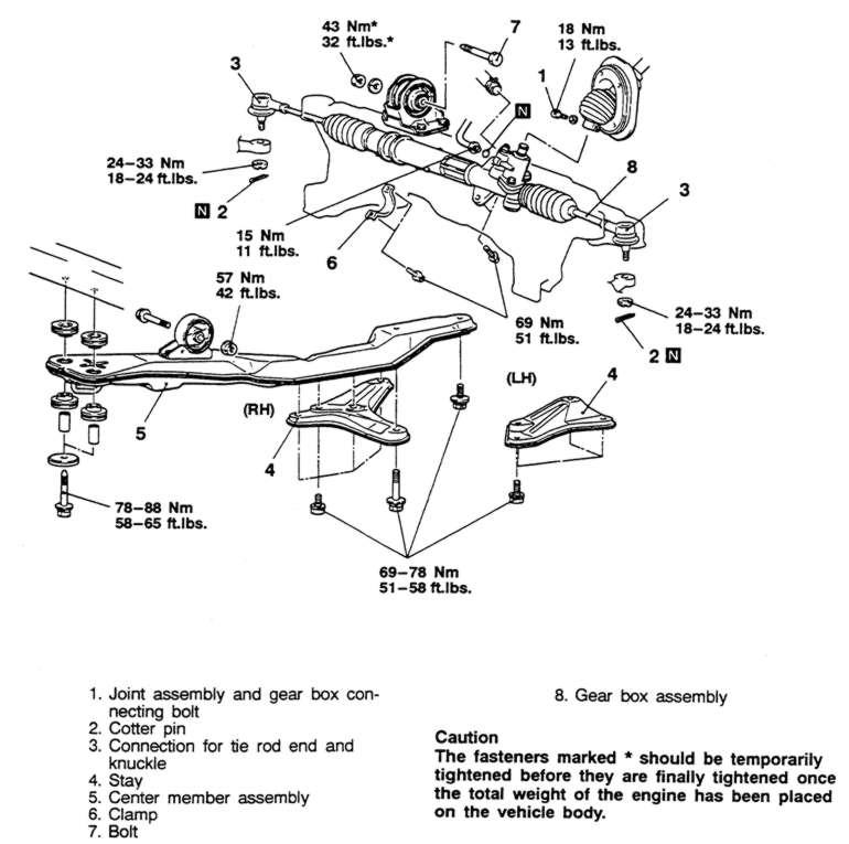
| Fig. 1: Exploded view of the power steering gear removal
procedure — Galant

|
WARNING
Prior to removal of the steering gear box, center the front wheels and remove
the ignition key. Failure to do so may damage the SRS clock spring and render
SRS system inoperative.
- Disconnect the negative battery cable.
- Raise and properly support the vehicle.
- Remove both front wheel assemblies.
- Remove the bolt holding lower steering column joint to the rack and pinion
input shaft.
- Remove the stabilizer bar.
- Remove the cotter pins, and using joint separator MB991113 or equivalent,
disconnect the tie rod ends from the steering knuckle.
- On vehicles equipped with Electronic Control Power steering (EPS), detach
the wiring harness from the solenoid connector.
- Locate the two triangular braces near the crossmember and remove both.
- Support the center crossmember. Remove the through-bolt from the front
round roll stopper and remove the bolts securing the center crossmember.
- Remove the center crossmember.
- Properly support the engine and remove the rear roll stopper through-bolt.
- Disconnect the power steering fluid pressure pipe and return hose from
the rack fittings. Plug the fittings to prevent excessive fluid leakage.
- Remove the clamp bolts and the two bolts securing the rack assembly to
the chassis.
- Remove the rack and pinion steering assembly and its rubber mounts.
NOTE: When removing the rack and pinion assembly, tilt
the assembly to the vehicle side of the compression lower arm and remove
from the left side of the vehicle.
To install:
- Center the rack assembly and insert the pinion into the steering column
shaft.
- Install the rack and mounting bolts. Tighten the mounting bolts to 51
ft. lbs. (69 Nm).
- Install the pinch bolt and tighten the bolt to 13 ft. lbs. (18 Nm).
- Connect the power steering fluid lines to the rack and tighten the pressure
hose fitting to 11 ft. lbs. (15 Nm). Secure the return hose with the clamp.
- Raise the engine into position.
- Install the rear roll stopper through-bolt and tighten to 32 ft. lbs.
(43 Nm).
- Raise the crossmember into position. Install the center member mounting
bolts; tighten the front bolts to 58–65 ft. lbs. (78–88 Nm)
and the rear bolt to 51–58 ft. lbs. (69–78 Nm).
- Install the front roll stopper bolt and tighten the nut to 32 ft. lbs.
(43 Nm).
- Install the two triangular braces and tighten the mounting bolts to 50–56
ft. lbs. (69–78 Nm).
- Install the stabilizer bar.
- Connect the tie rod ends and tighten the nuts to 20 ft. lbs. (27 Nm).
- On vehicles equipped with EPS, connect the wiring harness to the solenoid
connector.
- Install the wheel assemblies and lower the vehicle.
- Refill the reservoir with power steering fluid and bleed the system.
- Have a front end alignment performed.
- Disconnect the battery negative cable.
- Raise the vehicle and support safely.
- Remove the pinch bolt holding the lower steering column joint to the rack
and pinion input shaft.
- Remove the cotter pins and disconnect the tie rod ends from the steering
knuckle.
- Disconnect the power steering fluid pressure pipe and return hose from
the rack fittings.
- Remove the rack and pinion steering assembly and its rubber mounts.
To install:
- Install the steering gear into the vehicle and secure using the retainer
clamps and bolts.
- Connect the power steering fluid lines to the rack fittings.
- Install the stabilizer bar and rear transaxle bracket.
- Connect the tie rod ends to the steering knuckles.
- Connect the negative battery cable.
- Refill the reservoir and bleed the system.
- Have a front end alignment performed.
NOTE: Prior to removal of the steering gear box, center the
front wheels and remove the ignition key. Failure to do so may damage the
SRS clockspring and render SRS system inoperative.
- Drain the power steering system.
- Disconnect the battery negative cable. Raise the vehicle and support safely.
- Disconnect the Heated Oxygen (HO2S) sensor and remove the front exhaust
pipe.
- Properly support the engine.
- Remove both roll stopper mounting bolts and the four center member installation
bolts. Remove the center member.
- Remove the center member.
NOTE: Matchmark the pinion input shaft of the rack to
the lower steering column joint for installation purposes.
- Remove the pinch bolt holding the lower steering column joint to the rack
and pinion input shaft.
- Remove the cotter pins and disconnect the tie rod ends from the steering
knuckle.
- Disconnect the power steering fluid pressure pipe and return hose from
the rack fittings.
- Remove the rack and pinion steering assembly and its rubber mounts from
the right side of the vehicle.
To install:
- Align the matchmarks of the input shaft and install the rack to the vehicle.
- Secure the rack using the retainer clamps and bolts. Tighten the bolts
to 51 ft. lbs. (70 Nm).
- Tighten the steering column pinch bolt to 13 ft. lbs. (18 Nm).
- Using new O-rings, connect the power steering fluid lines to the rack
fittings.
- Install the center member.
- Install the front exhaust pipe.
- Connect the HO2S sensor.
- Connect the tie rod ends to the steering knuckles and tighten the castle
nuts to 25 ft. lbs. (34 Nm). Install new cotter pins.
- Install the wheels and connect the negative battery cable.
- Refill the reservoir and bleed the system.
- Have a front end alignment performed.
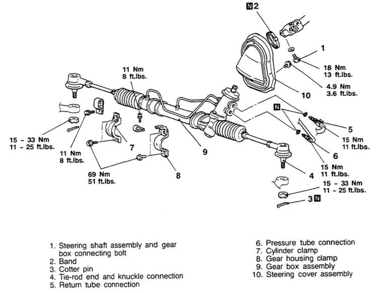
| Fig. 2: Exploded view of the power steering gear
assembly — Mirage

|