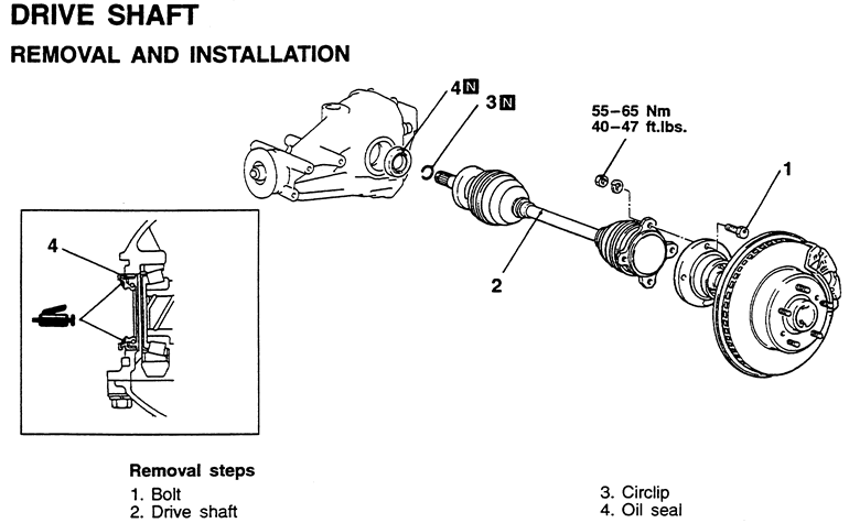
| Fig. 1: Front halfshafts and related components — 3000GT
|
- Before servicing the vehicle, refer to the precautions in the beginning
of this section.
- Disconnect the negative battery cable.
- Raise the vehicle and support safely. Remove the lower ball joint and the
tie rod end from the steering knuckle.
- Remove the cotter pin, halfshaft nut and the washer.
- On vehicles with an inner shaft, remove the center support bearing bracket
bolts and washers.
- On vehicles with an inner shaft, remove the halfshaft by setting up a puller
on the outside wheel hub and pushing the halfshaft from the front hub. Then,
tap the shaft union at the joint case with a plastic hammer to remove the
halfshaft shaft and inner shaft from the transaxle.
| Fig. 2: Front halfshaft removal — 3000GT
|
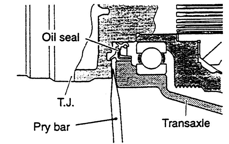
- On vehicles without an inner shaft, remove the halfshaft by setting up a
puller on the outside wheel hub and pushing the halfshaft from the front hub.
After pressing the outer shaft, insert a prybar between the transaxle case
and the halfshaft and pry the shaft from the transaxle. Do not pull on the
shaft.
To install:
- Replace the circlips on the ends of the halfshafts.
- Insert the halfshaft into the transaxle.
- Pull the strut assembly out and install the other end to the hub.
- Install or connect the following:
- Center bearing bracket bolts and tighten to 33 ft. lbs. (45 Nm)
- Washer so the chamfered edge faces outward. Tighten the nut to 188 ft.
lbs. (260 Nm)
- Tie rod end and ball joint
- Wheel and lower the vehicle
| Fig. 3: Exploded view of the front suspension
components — 3000GT
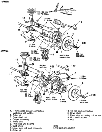
|
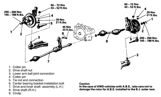
NOTE: On vehicles with a limited slip differential, the right
and left halfshafts are not the same. If both halfshafts are to be removed,
mark them for proper installation.
- Before servicing the vehicle, refer to the precautions in the beginning
of this section.
- Disconnect the negative battery cable. Raise the vehicle and support it
safely.
- Matchmark the halfshaft and the companion flange.
- Remove the bolts that attach the rear halfshaft to the companion flange.
- Use a prybar to pry the inner shaft out of the differential case.
- Remove the rear halfshaft from the vehicle.
To install:
- Install a new circlip on the halfshaft and install it into the differential.
Be sure it is fully seated.
- Align the matchmarks and attach the halfshaft to the companion flange. Tighten
the fasteners to 40–47 ft. lbs. (55–65 Nm).
- Lower the vehicle and connect the negative battery cable.
| Fig. 4: Rear halfshaft removal — AWD
3000GT

|
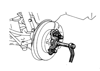
| Fig. 5: Proper method for disconnecting ball joint
studs and tie rod ends

|
- Before servicing the vehicle, refer to the precautions in the beginning
of this section.
- Raise the vehicle and support it safely.
- Remove the cotter pin, halfshaft nut and washer.
- If equipped with ABS, remove the front wheel speed sensor.
- If equipped with Active Electronic Control Suspension (Active-ECS) perform
the following:
- Loosen the nut that secures the air line to the to the top of the strut
and discard the O-ring.
- Remove the bolts that secure the actuator to the top of the strut and
remove the component. Disconnect the wiring harness.
- Disconnect the lower ball joint and the tie rod end from the steering knuckle.
- If removing the left side axle with an inner shaft, remove the center support
bearing bracket bolts and washers. Then, remove the halfshaft by setting up
a puller on the outside wheel hub and pushing the halfshaft from the front
hub. Tap the shaft union at the joint case with a plastic hammer to remove
the halfshaft and inner shaft from the transaxle.
- If removing right side axle shafts without an inner shaft, remove the halfshaft
by setting up a puller on the outside wheel hub and pushing the halfshaft
from the front hub. After pressing the outer shaft, insert a prybar between
the transaxle case and the halfshaft and pry the shaft from the transaxle.
NOTE: Do not pull on the shaft; doing so damages the inboard
joint.
To install:
- Replace the circlips on the ends of the halfshafts.
- Insert the halfshaft into the transaxle. Be sure it is fully seated.
- Pull the strut assembly out and install the other end to the hub.
- Install the center bearing bracket bolts and tighten to 33 ft. lbs. (45
Nm).
- Install the washer so the chamfered edge faces outward. Install the nut
and tighten to 145–188 ft. lbs. (200–260 Nm) and secure with a
new cotter pin.
- Connect the ball joint to the steering knuckle. Torque the new retaining
nut to 43–52 ft. lbs. (60–72 Nm) and secure with a new cotter
pin.
- Connect the tie rod end to the steering knuckle. Torque the retaining nut
to 21 ft. lbs. (29 Nm) and secure with a new cotter pin.
- If equipped with ABS, install the front wheel speed sensor.
- If equipped with Active-ECS, perform the following:
- Install the air line with a new O-ring.
- Install the actuator to the top of the strut. Connect the wiring harness.
- Install the wheel and lower the vehicle to the floor.
- Before servicing the vehicle, refer to the precautions in the beginning
of this section.
- Raise and safely support the vehicle.
- Remove or disconnect the following:
- Front wheel
- Halfshaft nut and washer
- Tie rod end from the knuckle
- Stabilizer link from the damper fork
- Compression and lateral arm ball joint studs from the knuckle
- Mount a puller on the wheel studs and push the halfshaft through the hub
assembly.
- Detach the inner halfshaft from the transaxle by carefully prying the CV-joint
housing out.
- Pull the knuckle assembly outward and remove the halfshaft.
To install:
- Place a new circlip on the inner halfshaft and install the halfshaft in
the transaxle.
- Push out on the knuckle assembly and install the halfshaft through the hub.
- Using new nuts, install the lateral and compression arm ball joint studs
in the knuckle. Tighten the nuts to 43–52 ft. lbs. (59–71 Nm).
Install new cotter pins.
- Install the damper fork on the knuckle. Do nut tighten the nut at this time.
- Attach the stabilizer link to the damper fork. Tighten the nut to 29 ft.
lbs. (39 Nm).
- Install the washer and nut on the halfshaft. Prevent the hub from turning
and tighten the nut to 145–188 ft. lbs. (196–255 Nm).
- Install the wheel and lower the vehicle to the floor. Tighten the damper
fork nut to 65 ft. lbs. (88 Nm).
| Fig. 6: Proper method for removing the inner halfshaft
from the transaxle or differential

|
- Before servicing the vehicle, refer to the precautions in the beginning
of this section.
- Raise and safely support the vehicle.
- Remove or disconnect the following:
- Rear wheel
- Rear wheel speed sensor, if equipped
- Caliper and rotor, if equipped with disc brakes
- Brake drum and shoes, If equipped with drum brakes
- Brake hydraulic line from the wheel cylinder
- Parking brake cable from the rear brakes
- Lower end of the shock absorber from the knuckle
- Trailing and lower arms from the knuckle
- Toe control arm ball joint from the knuckle
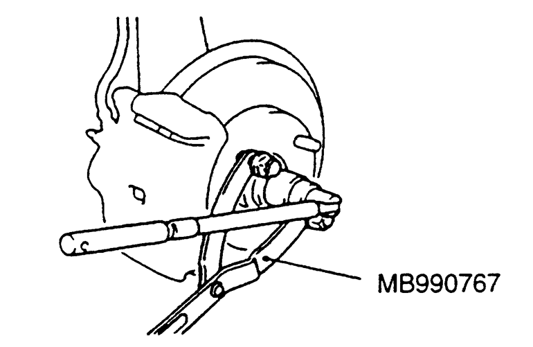
- Prevent the hub assembly from turning by using a tool such as MB990767 and
remove the halfshaft nut and washer.
- Remove the differential mount support.
WARNING
Do not pull on the halfshaft to remove it from the differential. Damage
to the inner CV-joint will occur.
- Push the lower part of the knuckle outward and pry the inner halfshaft out
of the differential.
- Push the outer end of the halfshaft through the hub/knuckle and remove it.
To install:
- Install the outer end of the halfshaft through the hub/knuckle.
- Place a new circlip on the inner halfshaft and install the halfshaft in
the differential.
- Install or connect the following:
- Differential mount support
- Washer and a new nut on the end of the halfshaft. Tighten the nut to
145–188 ft. lbs. (196–255 Nm).
- Toe control arm to the knuckle. Tighten the new nut to 20 ft. lbs. (28
Nm).
- Lower and trailing arms to the knuckle. Do not tighten the fasteners
at this time.
- Shock absorber. Tighten the bolt to 71 ft. lbs. (98 Nm).
- Assemble the brake components.
- Install or connect the following:
- Rear wheel speed sensor
- Rear wheel and lower the vehicle to the floor. Tighten the lower arm
nut to 71 ft. lbs. (98 Nm) and the trailing arm nut to 85–99 ft.
lbs. (118–137 Nm).