Previous Next

Camshaft and Valve Lifters

REMOVAL & INSTALLATION

2.4L Engine
  1. Before servicing the vehicle, refer to the precautions in the beginning of this section.
  2. Drain and recycle the engine coolant.
  3. Drain and recycle the engine crankcase.
  4. Remove or disconnect the following:

    CAUTION
    Wait at least 90 seconds after the negative battery cable is disconnected to prevent possible deployment of the air bag.

  5. Positive Crankcase Valve (PCV) hose
  6. Valve cover and the upper timing belt cover
  7. Rotate the crankshaft clockwise and align the camshaft sprocket timing mark with the timing mark on the cylinder head.
  8. Remove or disconnect the following:
  9. Install auto lash adjuster retainer MD998443 to each rocker arm to hold the auto lash adjusters in place
  10. Remove or disconnect the following:

    WARNING
    Do not rotate the crankshaft after the sprocket is removed from the camshaft. Be sure there is no slack in the timing belt. Be sure the timing belt does not disengage from the sprocket. If the crankshaft is rotated or the timing belt position is disturbed, timing belt and sprocket alignment will have to be set.

  11. Thrust cage and o-ring
  12. Camshaft and the front seal from the engine

    To install:

  13. Install or connect the following:
  14. Remove the auto lash adjuster retainer MD998443 from each rocker arm.
  15. Install or connect the following:
  16. Start the engine and check for leaks.
3.0L, 3.5L Engines
  1. Before servicing the vehicle, refer to the precautions in the beginning of this section.
  2. Relieve the fuel system pressure.
  3. Drain and recycle the engine coolant.
  4. Drain and recycle the engine crankcase.
  5. Remove or disconnect the following:

    CAUTION
    Work must be started after 90 seconds from the time the ignition switch is turned to the LOCK position and the negative battery cable is disconnected.

  6. Intake manifold plenum
  7. Valve cover
  8. Timing belt
  9. Sprocket from the camshaft
  10. Install auto lash adjuster retainers SST MD998443 on the rocker arms.
  11. Remove or disconnect the following:
  12. Inspect the bearing journals on the camshaft and the cylinder head.

    To install:

  13. Lubricate the camshaft journals and camshaft with clean engine oil
  14. Install or connect the following:
  15. Temporarily tighten the rocker shaft with the bolts positioned so that the intake valve rocker arms do not push the valves.
  16. Install or connect the following:
  17. Before installing the exhaust rocker arms and the rocker arm shaft, mount the rocker shaft spring.
  18. Remove the SST used to hold the lash adjuster in position.
  19. Check to ensure that the flat side of the rocker shaft is perpendicular to the cylinder head, and facing the valves.
  20. Gradually tighten the bearing caps in 2 or 3 steps. In the final step tighten to 23 ft. lbs. (31 Nm).
  21. Install or connect the following:
  22. Start the engine and check for leaks and proper operation.
  23. Refill the coolant and crankcase.

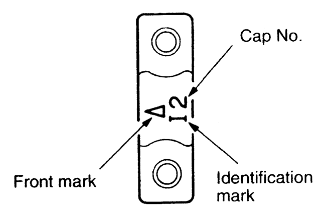
    Fig. 1: The camshaft bearing caps have identification marks on them — 3.5L engine

Previous Next