NOTE: The use of the correct special tools or their equivalent
is very important for this procedure. The head bolts used on some Mitsubishi
engines require a special hex wrench; the bolts' heads are round with internal
facets. Use tool MD 998051–01 or equivalent.Several external components
must be removed before the head can be removed. Refer to the necessary procedures
and use particular care during the timing belt removal and installation. Component
damage can result from improper work.
- Disconnect the negative battery cable.
- Drain the cooling system.
- Remove the carburetor from the intake manifold.
| Fig. 1: Cylinder head assembly — 2.0L
engine
|
| Fig. 2: Cylinder head bolt removal sequence — 2.0L
engine
|
| Fig. 3: Cylinder head gasket installation — 2.0L
engine
|
| Fig. 4: Cylinder head bolt torque sequence — 2.0L
engine
|
- Remove the intake manifold.
- Remove the exhaust manifold.
- Remove the radiator.
- Remove the engine fan and pulley.
- Remove the valve cover, labeling all lines and wires during disassembly.
- Remove the upper timing belt cover.
- Turn the motor until the timing marks align and the valves for cylinder
No.1 are closed (rockers are both loose). If the marks align, but the rockers
are not loose, turn the crankshaft another 360°. This will put the engine
at TDC compression on cylinder No. 1.
- Loosen and remove the bolt holding the upper timing belt sprocket to the
camshaft. Hold the sprocket inside the belt and maintain the tension on the
belt at all times. Carefully move the sprocket with the belt away from the
head and support it on the pad in the lower cover. It may be necessary to
use a small shim of soft material to keep the sprocket in position and under
tension.
WARNING
If the belt tension is lost or the sprocket fall out of place, the timing
belt must be reinstalled "from scratch'', requiring the removal of the lower
cover and other items.
- Double check the head to insure no remaining wires or hoses are connected.
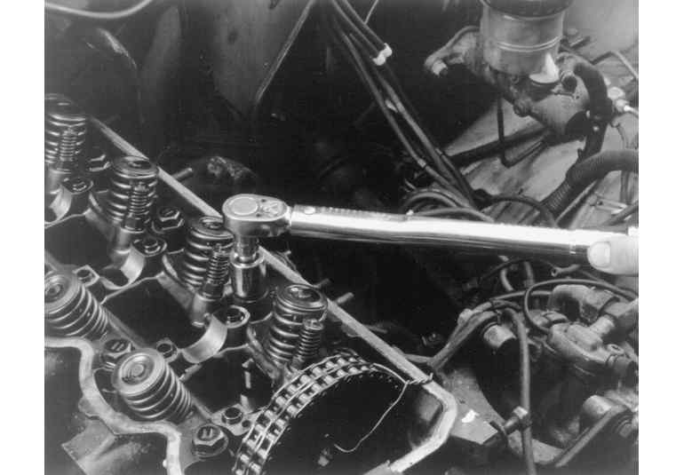
- Loosen the head bolts in the order shown (this is important) and in three
passes until all are finger loose. Remove the bolts.
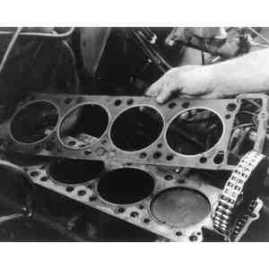
- Rock the head gently to break it loose; if tapping is necessary, do so with
a rubber or wooden mallet at the corners of the head. DO NOT pry the head
up by wedging tools between the head and the block.
- Lift the head free of the engine. Support it on wooden blocks on the workbench.
Refer to cleaning and inspection following this procedure for work to be done
before installing the head. If the head has been removed for work other than
gasket replacement, the rocker assembly and the camshaft may be removed.
To install:
- Place a new gasket onto the engine block. Make certain it is installed with
the identifying mark facing up (towards the head).
NOTE: Do not apply any sealant to the gasket or mating
surfaces of the head and block.
- Install the head straight down onto the block. Try to eliminate most of
the side–to–side adjustments as this may move the gasket out of
position. Install the bolts by hand and just start each bolt 1 or 2 turns
on the threads.
- The head bolt torque specification is 68 ft. lbs. (92 Nm). The bolts must
be tightened in order in two equal steps. On the first pass, tighten all the
bolts to 34 ft. lbs. (46 Nm); then proceed through the order again, tightening
each bolt to 68 ft. lbs. (92 Nm).
- Check that the cam and rocker position has not changed while the head was
removed. Carefully install the camshaft sprocket with the timing belt to the
camshaft. Tighten the retaining bolt to 65 ft. lbs. (88 Nm).
- Install the upper timing belt cover and the valve cover. This will protect
the valve train and timing belt from contamination during reassembly of other
components.
- Install the exhaust manifold with a new gasket.
- Install the intake manifold with a new gasket.
- Install the carburetor.
- Connect all wiring, hoses, and lines to the proper location. Double check
all connectors and clamps.
- Install the engine fan and pulley.
- Install the radiator.
- Double check all installation items, paying particular attention to loose
hoses or hanging wires, untightened nuts, poor routing of hoses and wires
(too tight or rubbing) and tools left in the engine area.
- Fill the cooling system with the proper coolant. Changing the engine oil
and filter is recommended to eliminate any contaminants in the oil.
- Connect the negative battery cable. Start the engine and check carefully
for leaks of oil, vacuum, fuel or coolant.
- Perform final engine adjustments as necessary.
- Disconnect the negative battery cable.
- Drain the coolant into clean containers for reuse.
- Remove the upper radiator hose from the engine.
- Label and disconnect the breather hoses running to the valve cover and across
the head.
| Fig. 5: Cylinder head bolt removal sequence — 2.3L
diesel engine
|
| Fig. 6: Cylinder head bolt torque sequence — 2.3L
diesel engine
|
- Disconnect the heater hose at the intake manifold.
- Disconnect the wiring to the temperature sensor.
- Disconnect and remove the inlet piping and the oil lines running to the
turbocharger. Make certain that both the lines and the turbocharger ports
are plugged or covered as soon as they are disconnected. NO foreign matter
is permitted in the turbocharger system.
- Carefully disconnect the fuel injection lines. See Section 5.
- Disconnect the glow plug connections.
- Remove the intake and exhaust manifolds.
- Remove the upper and lower timing belt covers. Turn the crankshaft and align
all the timing marks; this positions the motor at TDC/compression for No.
1 cylinder.
- Mark the direction of rotation on the timing belts with chalk or a felt
marker.
- Remove the center bolt holding the crankshaft pulley and remove the pulley.
Do not turn the engine out of position during this removal.
- Remove the lower timing belt cover.
- Slightly loosen the retaining (lock) bolts for the timing belt tensioner.
Move the tensioner towards the water pump and tighten the bolts; this holds
the tensioner in the slack position.
- Remove the camshaft sprocket and the injection pump sprocket. Do not let
either shaft turn out of place during the removal. Remove the timing belt
without forcing it or kinking it.
- Remove the fuel injection pump.
WARNING
Do not move or disturb the position of the engine once the timing belt is
removed!
- Remove the valve cover and gasket.
- Loosen the head bolts in the correct sequence. Loosen each bolt gradually
and in two or three passes. Sudden loosening of any bolt may cause head damage
by warping.
- Remove the head by lifting it off the engine; do not attempt to slide it
to the side.
- Remove the gasket. Clean the mating surfaces of all gasket remains. If the
head is to be off the engine for any length of time, plug the cylinders with
clean cloths or crumpled newspaper. Place the head on wood blocks on the work
bench for examination or further work. The head may be cleaned, inspected
or disassembled following instructions given later in this section.
To install:
- Before reinstallation, double check the head and block faces for any trace
of gasket material. Remove any plugs or paper from the head and/or cylinders.
- Place a new head gasket in position on the block. Pay close attention to
the alignment of the gasket with the holes and passages in the block. The
gaskets generally do not have any identifying marks for up or front. An incorrectly
installed gasket may block an oil or coolant passage.
- Place the head onto the block carefully; do not disturb the position of
the gasket. Start the head bolts in each hole by hand and turn them in 1 or
2 turns.
- Following the correct bolt–tightening pattern, tighten each bolt to
40 ft. lbs. (54 Nm). This is one half the final tension.
- Repeat the bolt tightening sequence, tightening each bolt to 80 ft. lbs.
(108 Nm) The acceptable range is 76–83 ft. lbs. (103–113 Nm).
- Install the crankshaft pulley; tighten the bolt to 52 ft. lbs. (70 Nm).
- Install the fuel injection pump.
- Move the timing belt tensioner all the way toward the water pump and temporarily
tighten it in this position.
- Install the timing belt onto the injection pump sprocket and camshaft sprocket,
making certain NOT to turn the crankshaft sprocket during the procedure. Make
certain there is no slack in the belt between the camshaft sprocket and the
injection pump sprocket.
NOTE: The injection pump sprocket tends to rotate during
this installation. Hold it in place while installing the timing belt.
- With the belt in place, check the alignment of the timing marks on both
sprockets. Loosen the tensioner mounting bolts which will apply tension to
the belt.
- Tighten the belt tensioner nut and bolt. Tighten the slot side bolt first,
then the fulcrum side. If it's done the other way, the adjuster will turn
and the belt will be too tight.
- Check the alignment of the timing marks.
- Using a wrench on the crankshaft bolt, turn the engine clockwise enough
to move the camshaft sprocket 2 teeth past the timing mark. Use the wrench
to reverse (counterclockwise) direction and turn the engine back to the original
position with the timing marks aligned.
- Use your finger to press down on the belt midway between the cam sprocket
and the injection pump sprocket. Deflection in the belt should be 0.16–0.20
in. (4–5mm).
- Install the valve cover.
- Install the upper and lower timing covers.
- Install the intake and exhaust manifolds. Always use new gaskets.
- Connect the fuel injection lines.
- Connect the wiring for the glow plug circuit.
- Install the turbocharger if it was removed from the manifolds. Remove any
plugs from the turbocharger passages; prime the unit by pouring a clean engine
oil into the turbocharger oil inlet port.
- Connect the oil drain hose and the oil inlet pipe to the turbocharger.
- Connect the turbocharger air inlet fitting and rubber hose (duct).
- Connect the temperature sensor lead. Connect the heater hose to the intake
manifold.
- Connect the breather and vacuum hoses as necessary.
- Install the upper radiator hose to the engine and make certain the clamp
is properly located and secure.
- Refill the cooling system with coolant.
- Connect the negative battery cable; start the engine and check for leaks
of fuel, oil or coolant.
- Check the injection timing, adjusting it if needed.
- Disconnect negative battery cable. Properly relieve the fuel system pressure.
- Drain the cooling system.
| Fig. 7: Cylinder head assembly — 2.4L
engine
|
| Fig. 8: Cylinder head bolt removal and torque sequence — 2.4L
engine
|
- Remove the upper radiator hose. Disconnect the heater hoses.
- Remove the air intake hose and pipe.
- Disconnect the accelerator, and if equipped, kickdown cable.
- Disconnect and plug the fuel lines.
- If equipped with power steering, unbolt the power steering pump from its
brackets and position it to the side.
NOTE: Do not disconnect the power steering lines.
- Remove the timing belt upper cover and valve cover.
- Rotate the crankshaft clockwise and align the timing mark on the camshaft
sprocket with the timing mark on the cylinder head.
- Remove the camshaft bolt.
- Remove the sprocket from the camshaft (with the timing belt attached) and
allow it to rest on the lower cover. Secure the belt to the sprocket so that
they do not become disengaged.
WARNING
Do not rotate the crankshaft after the camshaft sprocket is removed from
the camshaft. Secure the sprocket and timing belt so there is no slack in
the belt. Make sure the sprocket does not become disengaged from the timing
belt. If the engine is disturbed or the timing belt moved, the camshaft
timing will have to be reset.
- Label and disconnect the spark plug wires from the spark plugs. Remove the
distributor cap and wires.
- Mark the position of the rotor and distributor housing in relation to the
cylinder head and remove the distributor. If unfamiliar with the procedures
for removing the distributor, refer to those directions in Section 2.
- Label and disconnect all vacuum lines, hoses and wiring connectors from
the manifolds and cylinder head.
- Raise the vehicle and support safely.
- Remove the exhaust pipe from the exhaust manifold.
- Lower the vehicle.
- Remove cylinder head bolts, starting from the outside and working inward.
Remove the cylinder head from the engine.
- If necessary, remove the intake and exhaust manifolds from the cylinder
head.
- Clean the cylinder head gasket mating surfaces.
To install:
- If removed, install the intake and exhaust manifolds to the cylinder head,
using new gaskets.
- Install a new head gasket to the block and position the cylinder head assembly
with all head bolts and washers. tighten the bolts in sequence, in 2 or 3
steps, to 72 ft. lbs. (100 Nm).
- Install the camshaft sprocket to the camshaft and tighten the bolt to 72
ft. lbs. (100 Nm).
- Install the distributor, aligning the marks made during removal. Install
the distributor cap and spark plug wires.
- Install the power steering pump and adjust the belt tension.
- Connect the heater hoses and upper radiator hose.
- Install the valve cover and upper timing belt cover.
- Connect the fuel lines. Connect the accelerator, and if equipped, kickdown
cables.
- Connect all remaining wiring connectors, vacuum lines and hoses in their
proper locations.
- Install the air intake pipe and hose.
- Reconnect the exhaust system to the exhaust manifold.
- Refill the cooling system.
- Connect the negative battery cable.
- Start the engine and check for leaks. Check the ignition timing.
- Disconnect the negative battery cable.
- Drain the coolant.
| Fig. 9: Cylinder head bolt removal sequence — 2.6L
engine
|
| Fig. 10: Cylinder head gasket installation — 2.6L
engine
|
| Fig. 11: Cylinder head bolt torque sequence — 2.6L
engine
|
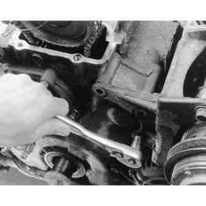
| Fig. 12: Detach any brackets which might be in the
way — 2.6L engine
|
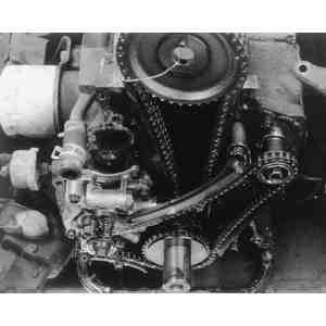
| Fig. 13: Remove the timing belt covers to access
the timing belt — 2.6L engine
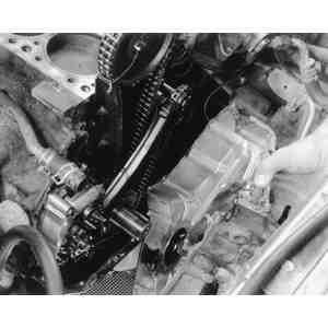
|
| Fig. 14: After removing the camshaft sprocket, secure
it to the chain and rest it on the lower pads — 2.6L
engine
|
| Fig. 15: Remove the cylinder head bolts, starting
with the two foremost bolts — 2.6L engine
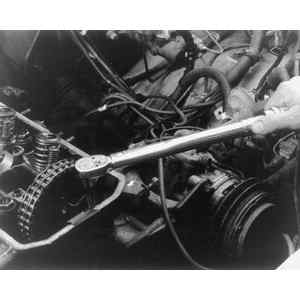
|
| Fig. 16: Loosen and remove the remaining cylinder
head bolts in the proper sequence — 2.6L engine
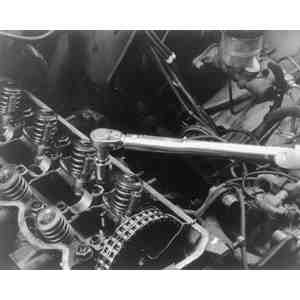
|
| Fig. 17: If removal of the cylinder head is difficult,
tap the corners with a wood or rubber mallet. Do not pry the head
off with anything — 2.6L engine
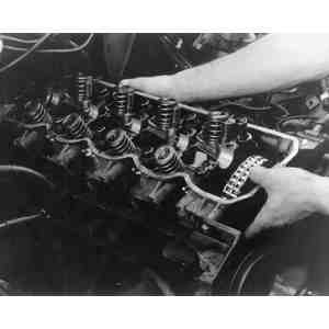
|
| Fig. 18: Remove the old gasket and dispose of it.
Use a new gasket upon installation — 2.6L engine
|
- Remove the air conditioner compressor drive belt.
- Remove the heat shield over the brake master cylinder.
- Disconnect the oxygen sensor harness connector and remove the heat shield
from the exhaust manifold.
- Remove the air cleaner assembly.
- Remove the upper radiator hose from the thermostat housing.
- Remove the air intake duct and the secondary air cleaner.
- Disconnect the PCV hose and accelerator cable from the valve cover. Remove
the valve cover and gasket. Remove the half-circle plug from the head.
- Turn the crankshaft clockwise to align the timing marks and set the engine
to TDC/Compression for No. 1 cylinder.
- Label and disconnect the coil and spark plug wires from the distributor.
- Disconnect the fuel lines.
- Disconnect the vacuum hose to the power brake booster from the engine. Disconnect
the heater hose and engine coolant hose at the rear of the engine.
- Remove the dipstick tube and dipstick. Discard the O-ring.
- Disconnect the rear (bottom) of the catalytic converter from the exhaust
system.
- Remove the distributor.
- Label and disconnect the vacuum hoses at or near the head.
- Label and disconnect the electrical connectors at the head and intake manifold.
Remember the connectors on the rear of the head, too.
- Remove the ground cable connection at the engine.
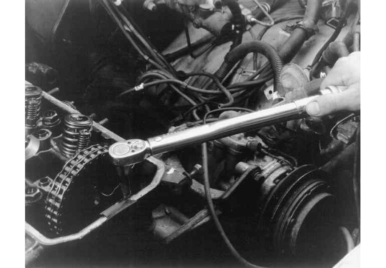
- Remove the bolt holding the camshaft sprocket to the camshaft. Remove the
distributor drive gear.
- Pull the camshaft sprocket (with the timing chain attached) from the camshaft
and place it on top of the camshaft sprocket holder.
WARNING
The crankshaft must not be rotated after the sprocket is removed from the
camshaft. Do not allow the timing chain to come off the camshaft sprocket.
- Double check the head to insure no remaining wires or hoses are connected.
- Loosen the head bolts in the order shown (this is important) and in three
passes until all are finger loose. Remove the bolts. Note that the two front
bolts must each be loosened before bolt No. 2 is loosened.
- Rock the head gently to break it loose; if tapping is necessary, do so with
a rubber or wooden mallet at the corners of the head. DO NOT pry the head
up by wedging tools between the head and the block.
- Lift the head free of the engine, remembering that the intake and exhaust
manifolds (with the catalytic converter) are still attached to the head. This
assembly is heavy; an assistant is helpful when lifting.Support the head assembly
on wooden blocks on the workbench. Refer to "Cleaning and Inspection'' following
this section for work to be done before installing the head. If the head has
been removed for work other than gasket replacement, the manifolds, rocker
assembly and the camshaft may be removed.
- Before placing a new gasket onto the engine block, apply 3M® ART
sealant No. 8660 or equivalent to the top surface of each joint between the
timing case and the cylinder block. Apply just enough sealant to fill the
seam and make certain NO sealant enters the oil passages in the block. Place
the new gasket on the block with the identifying mark facing up (towards the
head).
NOTE: Do not apply any sealant to the gasket or mating
surfaces of the head and block.
- Install the head straight down onto the block. Try to eliminate most of
the side–to–side adjustments as this may move the gasket out of
position. Install the bolts by hand and just start each bolt 1 or 2 turns
on the threads.
- The head bolt torque specification is 68 ft. lbs. (92 Nm). The bolts must
be tightened in the order shown in 3 steps. On the first pass, tighten all
the bolts to about 20 ft. lbs. (27 Nm) then proceed through the order tightening
each bolt to about 45 ft. lbs. (61 Nm). The final torque is achieved on the
third pass.
WARNING
The two bolts into the timing case are tightened ONLY to 13 ft. lbs. (19
Nm). Achieve this torque in steps of 4 ft. lbs. (5.4 Nm), 9 ft. lbs. (12
Nm) and 13 ft. lbs. (18 Nm). Do not overtighten these bolts.
- Check that the cam and rocker position has not changed while the head was
removed. Carefully install the camshaft sprocket with the timing chain to
the camshaft. Install the distributor drive gear and tighten the retaining
bolt to 40 ft. lbs. (54 Nm).
- Connect the engine ground strap and connect each electrical connector to
its proper component.
- Connect the vacuum hoses to the proper ports, making sure each is firmly
seated and not crimped or crushed.
- Install the distributor.
- Connect the catalytic converter to the exhaust system.
- Install a new O-ring on the dipstick tube and install the tube to the engine.
Make sure the O-ring is not damaged during installation.
- Connect the small coolant hose and the heater hose to the head or intake
manifold. Install the brake booster vacuum hose.
- Connect the fuel lines.
- Install the spark plug and coil wires.
- Install the half-circle plug with sealant. Install the valve cover and gasket.
- Install the accelerator cable and connect the PCV hose to the valve cover.
- Install the secondary air cleaner and connect the air intake ducts.
- Install the air cleaner assembly.
- Install the manifold heat shield and connect the oxygen sensor wiring.
- Install the heat shield on the brake master cylinder.
- Install and adjust the air conditioning compressor belt.
- Double check all installation items, paying particular attention to loose
hoses or hanging wires, untightened nuts, poor routing of hoses and wires
(too tight or rubbing) and tools left in the engine area.
- Fill the cooling system with the proper coolant. Changing the engine oil
and filter is recommended to eliminate any contaminants in the oil.
- Connect the negative battery cable. Start the engine and check carefully
for leaks of oil, vacuum, fuel or coolant.
- Perform final engine adjustments as necessary.
WARNING
The use of the correct special tools or their equivalent is most important for
this procedure. The camshaft sprocket must be removed and installed with the
use of tools MB 990767–01 and MB 998715 or their equivalents. Attempts
to use other tools or methods may cause damage to the sprocket and/or camshaft.
- Relieve the fuel system pressure.
- Disconnect the negative battery cable.
| Fig. 19: Cylinder head bolt removal sequence — 3.0L
and 3.5L engines
|
| Fig. 20: Cylinder head bolt installation torque sequence — 3.0L
and 3.5 engines
|
- Drain the cooling system. Remove the upper radiator hose.
- Remove the air intake hose.
- Remove the accessory drive belts, fan and pulleys.
- Remove the air conditioning compressor, power steering pump and mounting
brackets and position them to the side, without disconnecting the lines.
- If removing the right cylinder head, disconnect the wiring and remove the
alternator cover, alternator and alternator stay.
- Remove the timing belt covers.
- Remove the timing belt as follows:
- Rotate the crankshaft and bring the piston in No. 1 cylinder to TDC
on the compression stroke. Align the camshaft and crankshaft sprocket
timing marks.
- Mark the timing belt in the direction of rotation for reinstallation
purposes.
- Loosen the timing belt tensioner bolt and turn the tensioner counterclockwise.
Remove the timing belt.
WARNING
Do not rotate the crankshaft or camshaft sprockets after the timing
belt has been removed.
- Label and disconnect the spark plug wires from the spark plugs.
- If removing the left cylinder head, remove the distributor cap (if so equipped).
Mark the position of the rotor and the distributor housing in relation to
the cylinder head, then remove the distributor. If unfamiliar with the distributor
removal procedures, refer to these directions in Section 2.
- Remove the valve cover.
- Remove the EGR pipe and the air intake plenum stays.
- Disconnect the accelerator and, if equipped, throttle control cable. Disconnect
and plug the fuel lines.
- Label and disconnect the wiring connectors, vacuum lines and hoses from
the air intake plenum, intake manifold and cylinder head.
- Remove the air intake plenum and intake manifold.
- Remove the exhaust manifold.
- If removing the right cylinder head, remove the dipstick tube.
- If necessary, remove the camshaft sprocket bolt and camshaft sprocket. Remove
the alternator bracket and/or timing belt rear cover.
- Remove the cylinder head bolts starting from the outside and working inward.
- Remove the cylinder head from the engine.
- Clean the gasket mounting surfaces.
To install:
- Install the new cylinder head gasket over the dowels on the engine block,
with the identification mark at front top.
- Install the cylinder head on the engine and tighten the cylinder head bolts
in sequence using 3 even steps, to 65–72 ft. lbs. (90–100 Nm)
for all vehicles up to 1991. On all 1992–95 engines, tighten cylinder
head bolts in sequence using 3 steps to 76–83 ft. lbs. (103–113
Nm).
- If removed, install the timing belt rear cover and/or alternator bracket.
tighten the alternator bracket bolts in the proper sequence.
- If removed, install the dipstick tube using a new O-ring coated with clean
engine oil.
- Install the exhaust manifold.
- Install the intake manifold and air intake plenum.
- Install the EGR pipe and air intake plenum stays.
- Connect the fuel lines, accelerator and, if equipped, throttle control cable,
wiring connectors, vacuum lines and hoses.
- Install the valve cover.
- Install the distributor (if so equipped), if removed, aligning the marks
made during removal. Install the distributor cap and spark plug wires.
- Make sure the camshaft and crankshaft sprocket timing marks are aligned.
- Install the timing belt. Refer to the timing belt procedures later in this
section.
- Install the timing belt covers.
- If removed, install the alternator, alternator cover and alternator stay.
- Install the air conditioning compressor and power steering pump with the
brackets.
- Install the pulleys, cooling fan and accessory drive belts. Tighten the
crankshaft pulley bolt.
- Install the upper radiator hose and the air intake hose.
- Fill the cooling system.
- Connect the negative battery cable.
- Start the engine and check for leaks. Check the ignition timing.