NOTE: The 1993–95, rear-wheel drive 2.4L (California)
Pick-ups have the same engine controls as the 3.0L engines. All other 2.4L engines
are listed as 2.4L engines.
- With the MFI relay harness unplugged from the relay and the ignition switch
on, measure the power supply voltage to terminal 8 of the harness connector.
If there is no voltage present, the problem lies in the ignition switch or
in the harness between the ignition switch and the MFI relay connector, these
should be repaired or replaced as needed.
| Fig. 1: The MFI harness connector and terminal identification — 2.4L
engines
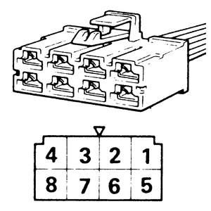
|
- Check for continuity of the ground circuit on terminal 6 of the MFI relay
harness connector. The ignition should be OFF and the MFI
relay still unplugged. If continuity is present, stop the check, the problem
lies elsewhere. If there is no continuity, repair or replace the harness between
the MFI relay and ground.
- With the MFI connector still unplugged, measure the power supply voltage
of terminal 4 of the MFI relay. If the power is not sufficient (the power
is the voltage of the battery, therefore around 10–12 volts), repair
the harness between terminal 4 and the battery.
- Disconnect the Engine Control Module (ECM) connector, and the MFI relay
connector should still be unplugged. Check for an open-circuit, or short-circuit
to ground, between the ECM (terminals 102 and 107) and the MFI relay (terminal
3). If an open-circuit is found, repair the harness between the ECM and terminal
3 of the MFI relay. If no short-circuit is found, the component is OK.
When performing these checks, use a harness side connector to fasten onto the
different terminals.
- Disconnect the ECM harness. Measure the ignition switch-IG terminal (terminal
110) input voltage. With the ignition switch OFF, the voltage
should be 0–1 volts. When the ignition switch is ON, the
voltage should be that of the battery (around 10–12 volts). If the circuit
shows these voltages, go on to Step 2, otherwise repair the harness between
terminal 110 and the ignition switch.
- Turn the ignition switch OFF and unplug the MFI relay connector.
Measure the power supply voltage of the MFI relay (terminal 10 to ground).
If the voltage is that of the battery, continue on to Step 3, otherwise repair
the harness between terminal 10 and the battery.
| Fig. 2: The numbered terminal locations on the MFI
harness connector — 3.0L (12 valve) engines
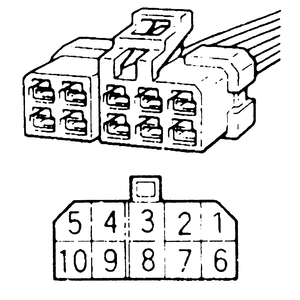
|
- With both the ECM and the MFI relay connectors unplugged, check for an open-circuit
or a short-circuit to ground between the MFI relay (terminal 8) and the ECM
(terminals 66 and 63). If no short-circuit is found, move on to Step 4, otherwise
repair the harnesses between terminal 8 and terminals 66 and 63.
- Keep both the ECM and the MFI relay connectors unplugged and check for an
open-circuit between terminal 4 of the MFI and terminals 102 and 107 of the
ECM. If a short-circuit is found, repair the harnesses between the terminals,
otherwise go on to Step 5.
- Connect the ECM and the MFI relay. While cranking the engine to start it,
measure the power supply voltage of the actuator (terminal 5 of the MFI to
ground). The voltage should be 8 volts or higher. Once the engine is running,
race the engine and measure the voltage again. The voltage should be at the
battery level. If the voltage is not as indicated, either the ECM or the MFI
relay is defective.
When performing these checks, use a harness side connector to fasten onto the
different terminals.
- Disconnect the ECM harness. Measure the ignition switch-IG terminal (terminal
62) input voltage. With the ignition switch OFF, the voltage should
be 0–1 volts. When the ignition switch is ON, the voltage
should be that of the battery (around 10–12 volts). If the circuit shows
these voltages, go on to Step 2, otherwise repair the harness between terminal
62 and the ignition switch.
- Turn the ignition switch OFF and unplug the MFI relay connector.
Measure the power supply voltage of the MFI relay (terminals 4 and 8 to ground).
If the voltage is that of the battery, continue on to Step 3, otherwise repair
the harness between terminals 4 and 8 and the battery.
- With both the ECM and the MFI relay connectors unplugged, check for an open-circuit
or a short-circuit to ground between the MFI relay (terminal 6) and the ECM
(terminal 38). If no short-circuit is found, move on to Step 4, otherwise
repair the harnesses between terminal 6 and terminal 38.
- Keep both the ECM and the MFI relay connectors unplugged and check for an
open-circuit between terminal 2 of the MFI and terminals 12 and 25 of the
ECM. If a short-circuit is found, repair the harnesses between the terminals,
otherwise go on to Step 5.
- Connect the ECM and the MFI relay. While cranking the engine to start it,
measure the power supply voltage of the actuator (terminal 3 of the MFI to
ground). The voltage should be 8 volts or higher. Once the engine is running,
race the engine and measure the voltage again. The voltage should be at the
battery level. If the voltage is not as indicated, either the ECM or the MFI
relay is defective.
| Fig. 3: The MFI harness connector on 3.0L (24 valve)
and 3.5L engines — make certain that the wires for
testing are hooked to the correct terminals
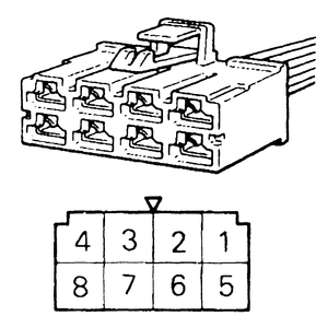
|

