Previous Next

KICKDOWN LINKAGE ADJUSTMENT

1983–86 Pick-Ups and Monteros

NOTE: When the idle speed is adjusted, the throttle linkage will need adjusting.

  1. Loosen the bolts so that rods B and C can slide properly.
  2. Allow the engine to warm up until the engine coolant temperature reaches the average operating temperature of 170°F (80°C). Confirm complete release of the fast idle. This confirmation can be made by checking to see if the cam surface of the choke lever of the carburetor is completely off the cam follower of the throttle lever.
  3. Lightly pushrod A or the transmission throttle lever toward the idle stopper (toward the back of the transmission), and set the rods to the idle position. Tighten the bolt securely to connect rods B and C.
  4. Make sure that, when the carburetor throttle valve is wide open, the transmission throttle lever moves with an operating angle of 47.5–54°of movement. Make sure that, when the throttle linkage alone is slowly returned from the fully opened position, the transmission throttle lever completely returns to idle by return spring force.

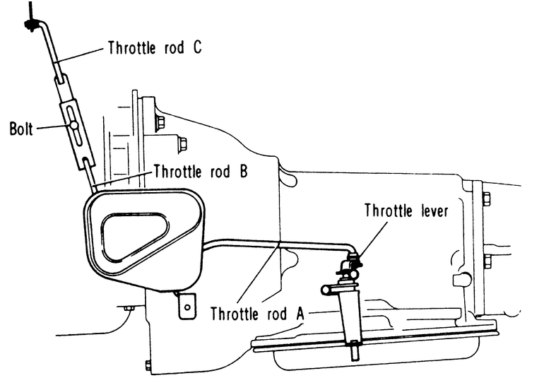
    Fig. 1: Throttle rod (kickdown) system — MA904A transmissions

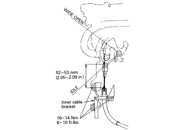
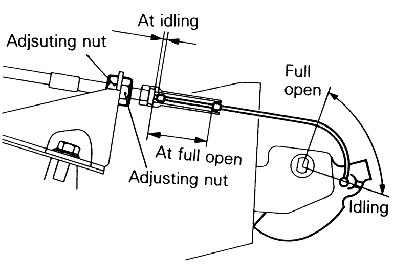
    Fig. 2: Check the movement range of the throttle lever on the transmission when finished adjusting the rods

1987–89 Pick-Ups and Monteros
  1. Check and adjust the idle speed.

    NOTE: When the engine idle adjustment has been performed, always adjust the throttle control cable.

  2. Make certain no bend or deformation is present in either the carburetor throttle lever or the cable mounting bracket.
  3. Measure the length between the inner cable stopper and the cover end with the throttle wide open.
  4. Correct measurement is 2.05–2.09 in. (52–53mm). If the cable is out of specification, adjust the inner cable bracket by moving it up or down as needed.

    Fig. 3: The kickdown adjustment set up on the AW372 and KM148 transmissions

1990–95 Pick-Ups
  1. Make sure that the kickdown cable is correctly attached to the bell crank lever.
  2. Pull on the inner kickdown cable (transmission end) while the throttle lever is held in the idle position.
  3. While the inner cable is being pulled, adjust the inner cable stopper so that the space between the stopper and the outer cable becomes 0.031–0.059 in. (0.8–1.5mm).
  4. Pull the inner cable (transmission end) and hold the throttle lever to the full open position. With this position being maintained, loosen and adjust the length of the bell crank lever arm so that the space between the inner cable stopper and the outer cable becomes 1.46–1.50 in. (37–38mm).
  5. After adjusting the engine to the regular idling position, fix the inner cable to the throttle lever (engine end of cable). At this time, fasten the outer cable with the adjusting nuts so that the space between the inner cable stopper and the outer cable becomes 0.031–0.05 in. (0.8–1.5mm).
  6. With the throttle lever (engine end) being fully open, confirm that the space between the outer cable and the inner cable is 1.30–1.38 in. (33–35mm).

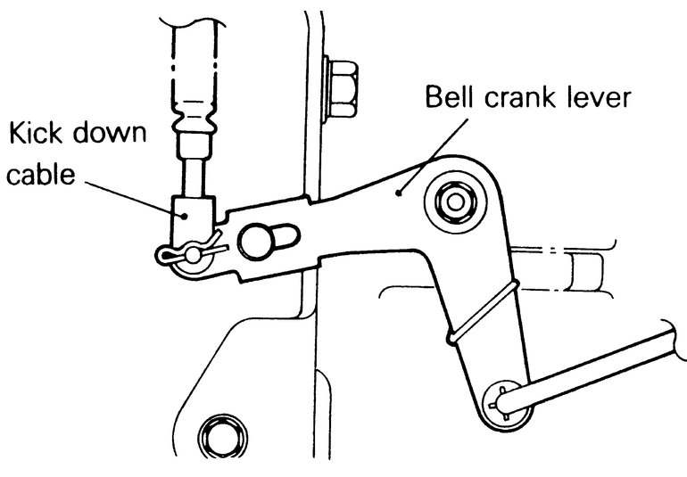
    Fig. 4: Make sure that the kickdown cable is securely attached to the bell crank lever before adjusting the cable

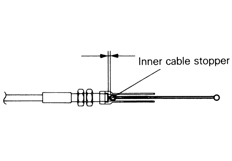
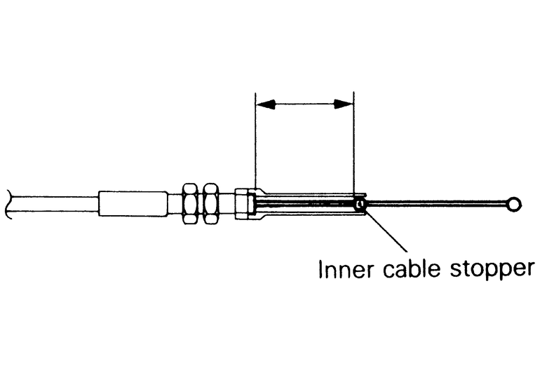
    Fig. 5: Move the inner cable stopper to change the clearance at idle — the clearance should be 0.8–1.5mm (0.031–0.05 in.)

    Fig. 6: Measure the clearance when the cable is pulled all the way to the wide open position

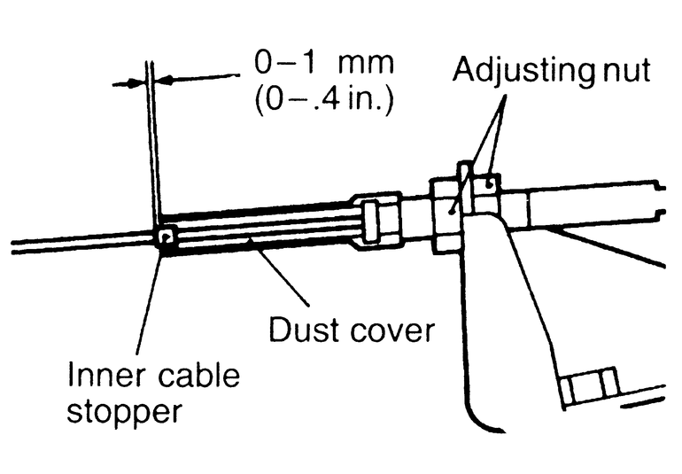
    Fig. 7: Once finished with the adjustment, check the clearances on the engine end of the cable

1990–95 Monteros
3.5L AND 1990–94 3.0L ENGINES
  1. Check for a defective or bent throttle lever or throttle cable bracket.
  2. With the accelerator depressed, check that the distance between the inner cable stopper and dust cover surface is within 0–0.4 in. (0–1mm).
  3. If the distance is outside of the standard value, adjust using the adjusting nut on the bracket.

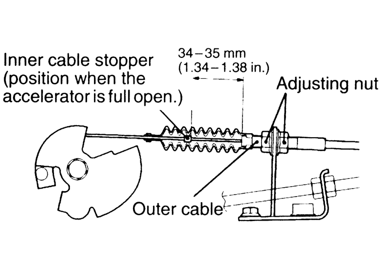
    Fig. 8: Adjust the clearance by turning the adjusting nut — 3.0L and 3.5L engines 1990–94

1995 3.0L ENGINES
  1. Make sure that the throttle lever and the bracket have no deformations or damage.
  2. Remove the boot at the outer cable so that the inner cable stopper can be seen.
  3. Measure the dimension between the end of the inner cable stopper and that of the outer cable with the throttle lever fully open. The standard value is 1.34–1.38 in. (34–35mm).
  4. If the distance is outside the standard value, adjust using the adjusting nut on the bracket.

    Fig. 9: To correctly adjust the cable, the boot must first be removed — adjust the cable by turning the adjusting nut

Previous Next