WARNING
Do not hot tank clean any aluminum parts or they will be ruined. Use carburetor
solvent for cleaning.
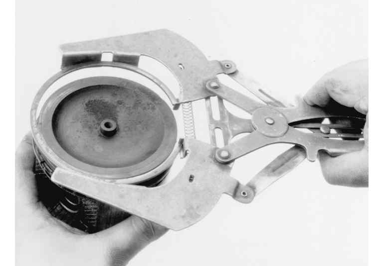
Using a piston ring expanding tool, remove the piston rings from the pistons; any other method (screwdriver blades, pliers, etc.) usually results in the rings being bent, scratched or distorted and/or the piston itself being damaged.
| Fig. 1: Using a ring expander tool to remove the piston
rings
|
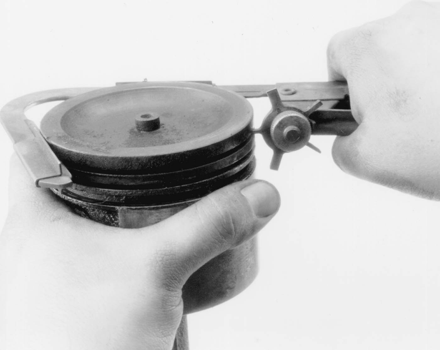
| Fig. 2: Clean the piston grooves using a ring groove
cleaner
|
Clean the varnish from the piston skirts and pins with a cleaning solvent.
DO NOT WIRE BRUSH ANY PART OF THE PISTON.
Clean the ring grooves with a groove cleaner and make sure that the oil ring holes and slots are clean.
Inspect the piston for cracked ring lands, scuffed or damaged skirts, eroded areas at the top of the piston. Replace the pistons that are damaged or show signs of excessive wear. Inspect the piston ring grooves for nicks or burrs that might cause the rings to hang up.
Measure the piston skirt perpendicular to the piston pin axis and note this figure for the piston clearance check. If installing replacement pistons, follow the manufacturers recommendations on where to measure the piston.
NOTE: 1970–75 models use cylinder liners. Later model engines use conventional cylinder bores. Refer to the appropriate procedure.
| Fig. 3: Cylinder bore inspection dimensions
|
Visually inspect the cylinder bores (liners) for roughness, scoring, or scuffing. If evident, the cylinder bore (liner) must be bored or honed oversize to eliminate imperfections, and the smallest possible oversize piston used. Since 1970–75 model engines use removable cylinder liners these can either be replaced or honed to oversize so long as the honing will not exceed 0.020 in. (0.508mm)
The new pistons should be given to the machinist with the block, so that the cylinders can be bored or honed exactly to the piston size (plus clearance). If no flaws are evident, measure the bore diameter using a telescope gauge and micrometer, or dial gauge, parallel and perpendicular to the engine centerline, at the top (below the ridge) and bottom of the bore. Subtract the bottom measurements from the top to determine taper, and the parallel to the centerline measurements from the perpendicular measurements to determine eccentricity. If the measurements are not within specifications, the cylinder must be bored or honed, and an oversize piston installed. If the measurements are within specifications the cylinder may be used as is, with only finish honing.
Using a telescoping gauge or an inside micrometer, measure the diameter of the cylinder bore, perpendicular (90°) to the piston pin, at 1–2 1⁄2 in. (25–64mm) below the surface of the cylinder block. The difference between the two measurements is the piston clearance.
If the clearance is within specifications or slightly below (after the cylinders have been bored or honed), finish honing is all that is necessary, If the clearance is excessive, try to obtain a slightly larger piston to bring the clearance within specifications. If this is not possible, obtain the first oversize piston and hone the cylinder or (if necessary) bore the cylinder to size.
When measuring the cylinder bore, take measurements in several places. If the cylinder bore is tapered or is out–of–round, it is advisable to rebore for the smallest possible oversize piston and rings. After measuring, mark the pistons with a felt-tip pen for reference during assembly.
NOTE: Boring of the cylinder block should be performed by a reputable machine shop with the proper equipment.
Wash the connecting rods in cleaning solvent and dry with compressed air. Check for twisted or bent rods and inspect for nicks or cracks. Replace the connecting rods that are damaged.
Install the cap on the rod and torque to specification. Using an inside micrometer, measure the inside bore diameter perpendicular (90°) to the axis of rod and once again along the axis of the rod. If the two measurements are not within specification, have the rod resized by a competent machine shop.
NOTE: It is normal for the inside diameter of the rod to be slightly larger when measured perpendicular (90°) to the axis of the rod.
Replacement bearings are available in standard size and undersize (for re-ground crankshafts). Connecting rod–to–crankshaft bearing clearance is checked using Plastigage® at either the top or the bottom of each crank journal. The Plastigage® has a range of 0.0010.003 in. (0.02540.0762mm).
NOTE: With the proper bearing selected and the nuts torqued, it should be possible to move the connecting rod back and forth freely on the crank journal as allowed by the specified connecting rod end clearance. If the rod cannot be moved, either the rod bearing is too far undersize or the rod is misaligned.
Measure the bearing journals at each end twice (90°apart) using a micrometer, to determine diameter, journal taper and eccentricity. The journal diameter is given in the Crankshaft Specifications chart earlier in this section. The taper limit is 0.008 in. (0.20mm) for 1970–76 models, 0.0028 in. (0.071mm) for 1977–84 models. The eccentricity limit is 0.0012 in. (0.030mm) The grinding limit is 0.0098 in. (0.248mm). Using a telescope gauge and micrometer, measure bearing I.D. parallel to piston axis and at 30°on each side of piston axis. Subtract journal O.D. from bearing I.D. to determine oil clearance. If crankshaft journals appear defective, or do not meet tolerances, there is no need to measure bearings, for the crankshaft will require grinding and/or undersize bearings will be required. If bearing appears defective, cause for failure should be determined prior to replacement.
Measure the oil clearance on each crankshaft bearing by means of Plastigage® as follows: Wipe off oil, dust, etc. on the surfaces to be measured. Install the bearings in the crankcase and set the crankshaft in position. Cut the Plastigage® to the bearing width and place it on the journal parallel with the crankshaft axis. Be careful not to put it on the oil hole or groove. Bring together the crankcase halves and tighten the bolts and nut to the specified torque.
NOTE: During the work, the crankshaft must not be turned nor the crankcase inverted.
Remove all the bolts and nut and separate the crankcase. Measure the Plastigage® width with the scale printed on the Plastigage® case. If the measurement is not within the specification, replace the defective bearing with an undersize one, and replace or recondition the crankshaft as necessary.
The piston ring end-gap should be checked while the rings are removed from the pistons. Incorrect end-gap indicates that the wrong size rings are being used; ring breakage could result if not corrected.