Previous Next

Halfshaft

REMOVAL & INSTALLATION

  1. Disconnect the negative (-) battery cable.
  2. Engage the parking brake. Remove the front wheel grease cap and the cotter pin.
  3. Loosen the wheel hub nuts and the halfshaft castle nut.

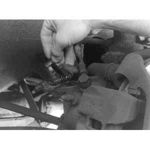
    Fig. 1: Remove the parking brake cable bracket from the transverse link

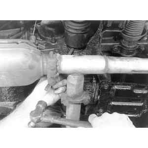
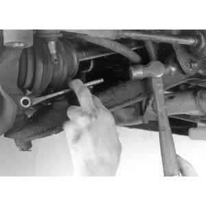
    Fig. 2: Using a pin punch, drive out the spring (roll) pin

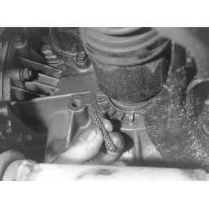
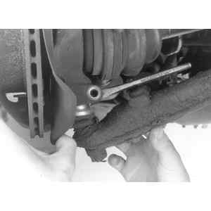
    Fig. 3: Close-up of the spring pin. Always use new pins when installing the shafts

  4. Raise and support the front of the vehicle with jackstands.
  5. Remove the wheel lug nuts, the wheel/tire assembly and the hub nut.
  6. Release the parking brake.
  7. Remove the parking brake cable bracket from the transverse link.
  8. Using a pin punch, drive out the Double-Offset Joint (DOJ)-to-transaxle shaft, spring (roll) pin; discard the old pin.

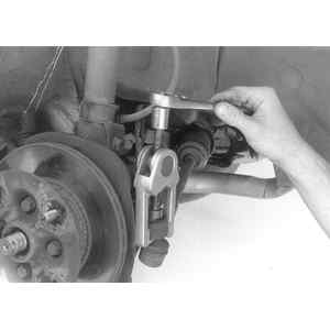
    Fig. 4: Using a ball joint puller tool, separate the tie-rod end from the steering knuckle

    Fig. 5: Using a cold chisel, drive it into the slit on the steering knuckle housing to expand the joint

    Fig. 6: Lower the transverse link from the steering knuckle

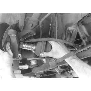
    Fig. 7: Push out on the housing to remove the halfshaft from the steering knuckle housing

  9. Remove the disc brake caliper-to-steering knuckle bolts and the brake caliper from the steering knuckle; using a wire, suspend it (DO NOT disconnect the brake hose) from the strut tower.
  10. Remove the damper strut-to-steering knuckle bolts.
  11. At the tie-rod end ball stud, remove the cotter pin and the castle nut.
  12. Using a Ball Joint Puller tool, remove the tie-rod end from the steering knuckle.
  13. Remove the transverse link ball stud-to-steering knuckle bolt. Using a cold chisel, drive it into the slit on the steering knuckle housing (to expand the joint), then lower the transverse link from the steering knuckle.
  14. Using the Puller tool No. 926470000 or equivalent, press the halfshaft from the steering knuckle housing.
  15. Clean and inspect the parts for wear and/or damage.

    To install:

  16. Install the halfshaft into the steering knuckle housing and attach the Installation Spacer tool No. 925130000 or 922430000 or equivalent, onto the outer bearing inner race; be careful not to damage the oil seal lip.
  17. Use a new spring pin and reverse the removal procedures.
  18. Tighten the transverse link ball joint-to-housing bolts to 22–29 ft. lbs. (29–39 Nm) and the damper strut-to-housing bolts to 22–29 ft. lbs. (29–39 Nm).
  19. Tighten the disc cover-to-housing bolts to 4–19 ft. lbs. (5–25 Nm) and the steering knuckle housing-to-halfshaft nut to 145 ft. lbs. (196 Nm)

    NOTE: After tightening the halfshaft nut to specifications, retighten it another 30 degrees further.

Previous Next