CAUTION
The clutch driven disc may contain asbestos, which has been determined to be
a cancer causing agent. Never clean clutch surfaces with compressed air! Avoid
inhaling any dust from any clutch surface! When cleaning clutch surfaces, use
a commercially available brake fluid.
| Fig. 1: Clutch system components — mechanical
clutch
|
| Fig. 2: Clutch system components — hydraulic
clutch
|
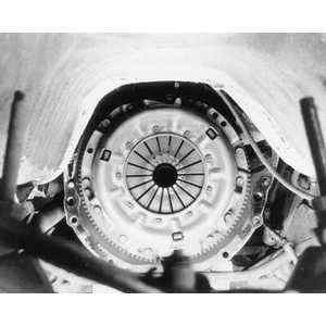
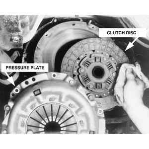
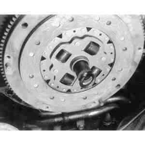
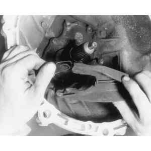
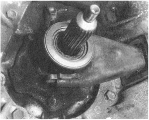
| Fig. 3: View of the clutch and pressure plate assembly
|
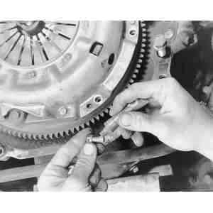
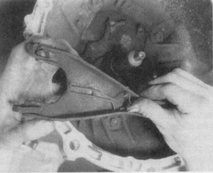
| Fig. 4:Loosen and remove the clutch and pressure plate
bolts evenly, a little at a time . . .
|
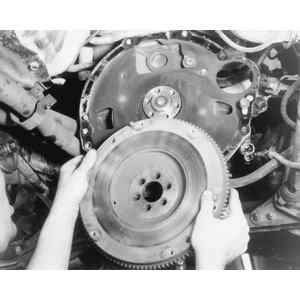
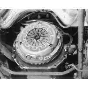
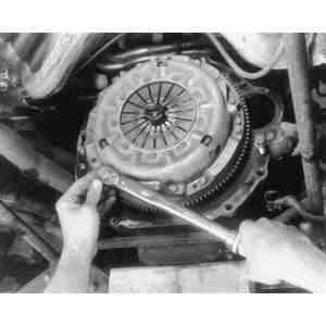
| Fig. 5:. . . then carefully removing the clutch and pressure
plate assembly from the flywheel
|
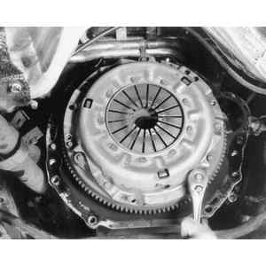
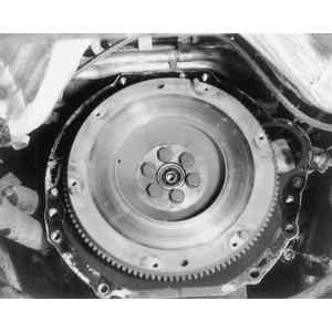
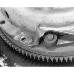
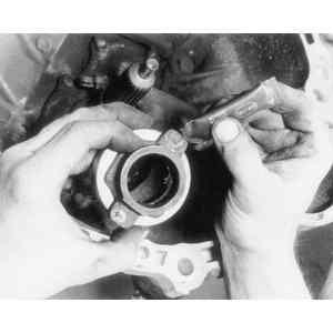
| Fig. 6:The flywheel is accessible once the clutch assembly
is removed
|
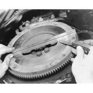
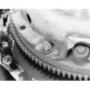
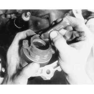
| Fig. 7:Check across the flywheel surface, it should be
flat
|
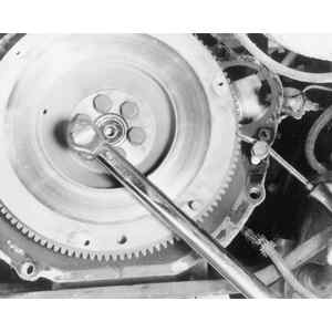
| Fig. 8:If necessary, lock the flywheel in place and remove
the retaining bolts . . .
|
| Fig. 9:. . . then remove the flywheel from the crankshaft
in order replace it or have it machined
|
| Fig. 10:Upon installation, it is usually a good idea
to apply a threadlocking compound to the flywheel bolts
|
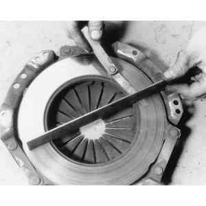
| Fig. 11:Check the pressure plate for excessive wear
|
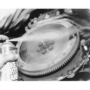
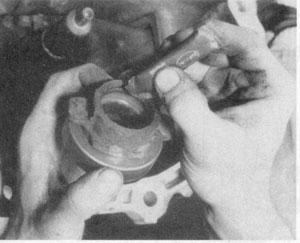
| Fig. 12:Be sure that the flywheel surface is clean, before
installing the clutch
|
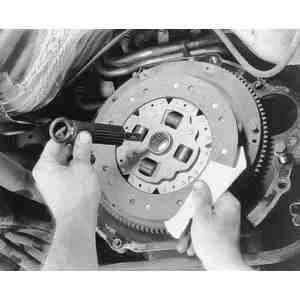
| Fig. 13:Install a clutch alignment arbor, to align the
clutch assembly during installation
|
| Fig. 14:Clutch plate installed with the arbor in place
|
| Fig. 15: Clutch plate and pressure plate installed with
the alignment arbor in place
|
| Fig. 16:Pressure plate-to-flywheel bolt holes should
align
|
| Fig. 17:You may want to use a threadlocking compound
on the clutch assembly bolts
|
| Fig. 18: Install the clutch assembly bolts and tighten
in steps, using an X pattern
|
| Fig. 19:Be sure to use a torque wrench to tighten all
bolts
|
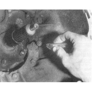
| Fig. 20:Grease the clutch release fork ball
|
| Fig. 21:Check the clutch release fork for signs of damage
|
| Fig. 22:Make sure the clutch release fork bearing clips
are not bent or broken
|
| Fig. 23:Grease the throwout bearing assembly at the outer
contact points
|
| Fig. 24:Grease the throwout bearing assembly at the inner
contact points
|
| Fig. 25:Installing the clutch release fork bearing clip
|
| Fig. 26:Be sure all parts move freely
|
WARNING
Do not get oil or grease on the clutch facing.
NOTE: Do not disassemble either the clutch cover or disc. Inspect the parts for wear or damage and replace any parts as necessary. Replace the clutch disc if there is any oil or grease on the facing. Do not wash or attempt to lubricate the throwout bearing. If it requires replacement, the bearing may be removed and a new one installed in the holder by means of a press.
To install:
WARNING
When installing the clutch pressure plate assembly, make sure that the
O marks on the flywheel and the clutch pressure plate assembly are at least 120°apart. These marks indicate the direction of residual unbalance. Also, make sure that the clutch disc is installed properly, noting the FRONT and REAR markings.