| Fig. 1: Front suspension assembly — Justy
|
NOTE: Do not remove the large nut on top of the strut assembly
unless the coil spring is properly compressed with a suitable spring compressor.
- Disconnect the negative battery cable.
- Raise and safely support the vehicle on jackstands.
- Remove the tire and wheel assembly.
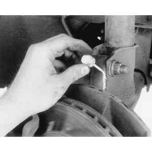
- Disconnect and cap the front brake hose at the strut mounting bracket.
- Remove the bolt that secures the brake hose to the strut.
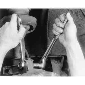
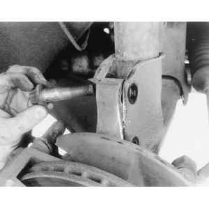
- Remove the lower strut pinch bolt.
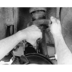
- Using a suitable tool, slightly wedge open the lower strut mounting bracket,
and slide the strut assembly out.
- Lower the vehicle enough to open the hood.
- Remove the upper strut plate mounting nuts.
- Lower the strut assembly out of the vehicle.
To install:
- Install the strut in the vehicle so the upper strut plate bolts pass through
the strut tower bolt holes. Install the mounting nuts and tighten to 10 ft.
lbs. (14 Nm).
- Raise and safely support the vehicle.
- Guide the lower end of the strut into the steering knuckle. Install the
pinch bolt and tighten to 32 ft. lbs. (44 Nm).
- Install the bolt that secures the brake hose to the strut and tighten to
32 ft. lbs. (44 Nm).
- Install all remaining components in the reverse order of removal. Bleed
the brake system. Have the front end alignment checked by a qualified professional.
| Fig. 2: Front standard suspension assembly — Sedan
Coupe, Loyale, XT, Wagon and Brat
|
| Fig. 3: Front brake hose connection points
|
| Fig. 4: Removing the front brake cable from the caliper
|
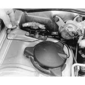
| Fig. 5: Bearing cap retainer nuts in engine compartment
|
NOTE: Do not remove the large nut on top of the strut assembly
unless the coil spring is properly compressed with a suitable spring compressor.
- Disconnect the negative battery cable.
- Raise and safely support the vehicle safely on jackstands.
- Remove the front wheel and tire assembly.
- Disconnect and cap the front brake hose from the caliper.
- Remove the brake hose securing clip from the strut bracket and remove the
hose from the bracket.
- Disconnect the parking brake cable from the caliper, if equipped.
- Open the hood.
- Loosen the nuts which connects the strut bearing cap to the upper housing
in the engine compartment.
- Loosen and remove the strut-to-steering knuckle retainer nuts and bolts.
- Disconnect the strut from the steering knuckle.
- Remove the upper strut mounting nuts.
- Remove the strut assembly from the vehicle.
To install:
- Position the strut in the vehicle, and install the upper strut mounting
nuts. Tighten the nuts to 27 ft. lbs. (36 Nm).
- Attach the strut assembly to the steering knuckle. Connect the strut-to-the
steering knuckle nuts and bolts. Tighten the nuts and bolts to 37 ft. lbs.
(50 Nm). Install and secure all remaining components in the reverse order
of removal.
- Bleed the brake system and have the front end alignment checked by a qualified
professional.
| Fig. 1: Front pneumatic suspension assembly—Sedan,
Coupe, Loyale, XT, Wagon and Brat
|
- Disconnect the negative battery cable.
- Raise and safely support the vehicle safely on jackstands.
- Remove the front wheel and tire assembly.
- Disconnect and cap the front brake hose from the caliper.
- Remove the brake hose securing clip from the strut bracket and remove the
hose from the bracket.
- Disconnect the parking brake cable from the caliper, if equipped.
- Open the hood.
- Disconnect the air line from the solenoid valve or top of the shock.
- Disconnect the height adjustment harness at the top of the shock.
- Loosen the nuts which connects the strut bearing cap to the upper housing
in the engine compartment.
- Loosen and remove the strut-to-steering knuckle retainer nuts and bolts.
- Disconnect the strut from the steering knuckle.
- Remove the upper strut mounting nuts.
- Remove the strut assembly from the vehicle.
To install:
- Position the strut in the vehicle, and install the upper strut mounting
nuts. Tighten the nuts to 27 ft. lbs. (36 Nm).
- Attach the strut assembly to the steering knuckle. Connect the strut-to-the
steering knuckle nuts and bolts. Tighten the nuts and bolts to 37 ft. lbs.
(50 Nm). Install and secure all remaining components in the reverse order
of removal.
- Bleed the brake system. Start the vehicle and allow enough time for the
strut to pressurize before driving. Have the front end alignment checked by
a qualified professional.
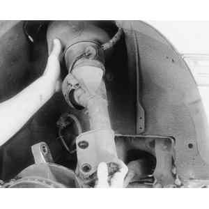
| Fig. 7: Front suspension assembly — Legacy
and Impreza
|
| Fig. 8: Paint an alignment mark between the strut and
steering knuckle assembly to ease realignment
|
| Fig. 9: Loosen the upper strut-to-steering knuckle retainer
nut and bolt
|
| Fig. 10: Loosen the lower strut-to-steering knuckle nut
and bolt
|
| Fig. 11: Remove the retainer bolts. The upper bolt's
eccentric shaft allows camber adjustment
|
| Fig. 12: Lower the strut assembly out of the vehicle
|
NOTE: Do not remove the large nut on top of the strut assembly
unless the coil spring is properly compressed with a suitable spring compressor.
- Disconnect the negative battery cable.
- Raise and support the vehicle safely.
- Remove the front wheel assembly.
- Disconnect the ABS sensor, if equipped.
- Remove the caliper, leaving the line connected and suspend it out of the
way with a piece of wire or string.
- Remove the clip attaching the brake line to the strut housing.
- Matchmark the camber adjustment bolt to the strut housing as reference for
installation.
- If equipped with ABS, remove the bolt securing the sensor harness.
- Remove the two bolts and nuts securing the strut to the steering knuckle.
Notice that the shaft of the top bolt is not round. This bolt is used for
camber adjustment, and most always be installed in the top hole.
- Remove the three nuts securing the strut to the body in the engine compartment.
- Remove the strut and coil spring assembly from the vehicle.
- Installation is the reverse of removal. Secure the upper strut retainer
nuts to 15 ft. lbs. (20 Nm).
- If equipped, install the ABS sensor harness, and tighten the bolt to 14
ft. lbs. (20 Nm).
- Install the lower strut nuts and bolts. Make sure the alignment adjustment
bolt is installed in the top mounting hole. Tighten the nuts, while securing
the bolts to 112 ft. lbs. (152 Nm).
- Have the front wheel alignment checked by a qualified professional.
| Fig. 13: Front pneumatic suspension assembly — Legacy
and Impreza
|
| Fig. 14: Disconnect the air line from the solenoid valve — Legacy
shown
|
| Fig. 15: Remove the plastic cover over the strut bearing
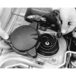
|
| Fig. 16: Loosen the bearing cap retainer nuts
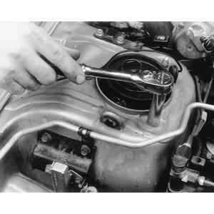
|
| Fig. 17: Lower the strut assembly from the vehicle
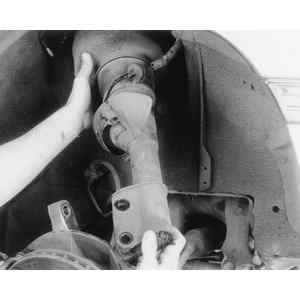
|
- Disconnect the negative battery cable.
- Raise and support the vehicle safely.
- Remove the front wheel assembly.
- From inside the engine compartment, disconnect the air line and height sensor
harness from the strut assembly.
- Disconnect the ABS sensor, if equipped.
- Remove the caliper, leaving the line connected and suspend it out of the
way with a piece of wire or string.
- Remove the clip attaching the brake line to the strut housing.
- Matchmark the camber adjustment bolt to the strut housing as reference for
installation.
- If equipped with ABS, remove the bolt securing the sensor harness.
- Remove the two bolts and nuts securing the strut to the steering knuckle.
Notice that the shaft of the top bolt is not round. This bolt is used for
camber adjustment, and most always be installed in the top hole.
- Remove the three nuts securing the strut to the body in the engine compartment.
- Remove the strut and coil spring assembly from the vehicle.
To install:
- Install the strut assembly into the vehicle. Secure the upper strut retainer
nuts to 15 ft. lbs. (20 Nm).
- If equipped, attach the ABS sensor harness, and tighten the bolt to 14 ft.
lbs. (20 Nm).
- Install the lower strut nuts and bolts. Make sure the alignment adjustment
bolt is installed in the top mounting hole. Tighten the nuts, while securing
the bolts to 112 ft. lbs. (152 Nm).
- Install and secure all remaining components in the reverse order of removal.
Start the vehicle and allow enough time for the strut to pressurize before
driving.
- Have the front wheel alignment checked by a qualified professional.
| Fig. 1: Front suspension assembly—SVX
|
NOTE: Do not remove the large nut on top of the strut assembly
unless the coil spring is properly compressed with a suitable spring compressor.
- Disconnect the negative battery cable.
- Raise and safely support the vehicle on jackstands.
- Remove the tire and wheel assembly.
- Disconnect the sway bar from the strut assembly.
- Remove the bolt and bracket securing the ABS sensor wire to the strut assembly.
- Remove the bolt and bracket securing the brake hose to the strut.
- Scribe matchmarks on the camber adjusting bolt and the steering knuckle
for installation purposes.
- Remove the nuts from the lower strut mounting bolts. Remove the lower mounting
bolt. The upper bolt MUST remain in place.
- Support the lower control arm under the ball joint with a suitable jack.
- Remove the strut mount cap in the engine compartment.
- Remove the three strut plate mounting nuts.
- Lower the jack about an inch and remove the strut-to-steering knuckle upper
mounting bolt.
- Remove the strut from the vehicle.
- If the strut is to be replaced, remove the sway bar link.
To install:
- Install the sway bar link on the strut and tighten the mounting nut to 28
ft. lbs. (37 Nm).
- Install the strut assembly into the vehicle and install the upper mounting
nuts and tighten to 30 ft. lbs. (41 Nm). Install the strut mount cap.
- Connect the strut to the steering knuckle and install the lower mounting
through-bolts and loosely install the nuts. Remove the jack. Next, rotate
the camber adjusting bolt so the matchmarks are in alignment. Tighten the
mounting nuts to 112 ft. lbs. (152 Nm).
- Install and secure all remaining components in the reverse order of removal.
Check the front end alignment and adjust as necessary.