Previous Next

Power Steering Gear

REMOVAL & INSTALLATION

Sedan, Coupe, Loyale, XT, Wagon and Brat
  1. Disconnect the negative battery cable.
  2. Remove the spare tire.
  3. Remove the spare tire support (turbo engines only).
  4. Disconnect the thermo-sensor connector.
  5. Raise and safely support the vehicle.
  6. Remove the front wheels.
  7. Remove the front exhaust pipe assembly.
  8. Remove the cotter pins and castle nuts from the outer tie rod ends. Using a suitable puller disconnect the tie rod ends from the steering knuckles.
  9. Remove the jack up plate.
  10. Disconnect the pipe joint at the center of the rack and connect a vinyl hose to the pipe and joint. Turn the wheel side to side to push the fluid out of the rack. Repeat the same procedure on the second line.
  11. Remove the lower universal joint pinch bolt then remove the upper bolt and push the universal joint upward.
  12. Remove the remaining two lines from the rack and pinion unit.
  13. Remove the rack and pinion mounting bolts and remove the rack and pinion assembly.
  14. Installation is the reverse of removal. Secure all components accordingly.
  15. Refill the power steering system and start the vehicle and check for leaks. Check the fluid and top off as necessary.
Legacy

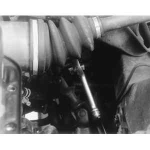
Fig. 1: Loosening the steering column-to-rack pinch bolt — Legacy

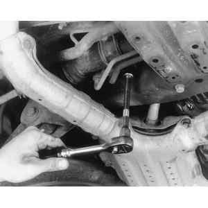
Fig. 2: Removing the steering rack retainer bolts

Fig. 3: Steering rack pressure pipes

Fig. 4: Disconnect pipe D first, followed by pipe C

  1. Disconnect the negative battery cable.
  2. Raise and support the vehicle safely.
  3. Remove the front tire and wheel assemblies.
  4. Disconnect the electrical connector from the oxygen sensor. Remove the front exhaust pipe assembly.
  5. Remove the tie rod end cotter pin and loosen the castle nut. Using a ball joint puller, separate the tie rod ends from the steering knuckle arm.
  6. Remove the jack up plate and the front stabilizer bar.
  7. From the power steering rack, remove the center pressure pipe, connect a vinyl hose to the pipe and joint, then turn the steering wheel to discharge the fluid into a container.

    NOTE: When discharging the power steering fluid (line A and B), turn the steering wheel fully, left and right. Be sure to disconnect the other pipe and drain the fluid in the same manner.

  8. From the control valve of the gearbox assembly, remove the power steering C and D pressure pipes. Remove pipe D first and pipe C second.
  9. If not disconnected when draining the fluid from the control valve of the gearbox assembly, remove the power steering A and B pressure pipes. Remove pipe A first and pipe B second.
  10. Remove the power steering gearbox to crossmember assembly bolts. Remove the gearbox assembly from the vehicle.

    To install:

  11. Install the power steering rack and tighten the rack to crossmember bolts to 35–52 ft. lbs. (47–70 Nm). When installing the universal joint assembly, be sure to align the matchmarks.
  12. Tighten the power steering pressure pipes 7–12 ft. lbs. (10–16 Nm), the universal joint assembly to power steering gearbox bolts 16–19 ft. lbs. (22–24 Nm) and the universal joint assembly to steering shaft bolts 16–19 ft. lbs. (22–24 Nm).
  13. Tighten the tie rod end to steering knuckle nut 18–22 ft. lbs. (25–29 Nm). After torquing this nut, turn it up to 60 degrees further to align the cotter pin hole. Install a new cotter pin.
  14. Install the tires and tighten the wheel lug nuts to specification.
  15. Refill and bleed the power steering system.
  16. Check and adjust the toe-in and the steering angle.
Impreza
  1. Disconnect the negative battery cable.
  2. Raise and support the vehicle safely.
  3. Remove the front wheels.
  4. Remove the front Y-pipe.
  5. Remove the tie rod end cotter pin and nut. Using a puller, disconnect the tie rod ends from the steering knuckle.
  6. Remove the jack-up plate and front sway bar.
  7. Disconnect the fluid lines from the rack and pinion.
  8. Matchmark the universal joint to the serration in the steering rack for installation reference.
  9. Remove the universal joint bolts and lift the joint upward disconnecting it from the rack and pinion shaft.
  10. Remove the clamps bolts securing the rack and pinion to the crossmember. Remove the rack and pinion.

    To install:

  11. Install the rack and pinion and tighten the clamp bolts to 43 ft. lbs. (59 Nm).
  12. Align the steering rack to the universal joint. Push the long yoke of the joint all the way into the serrated position of the steering shaft, setting the bolt hole in the cut-out. Pull the short yoke all the way out of the serrated portion of the rack and pinion, setting the bolt hole in the cut-out. Insert the bolt through the short yoke. Pull the yoke and ensure the bolt is properly engaged in the cut-out. Fasten the short yoke side with the spring washer and bolt, then fasten the yoke side. Tighten the bolts to 17 ft. lbs. (24 Nm). Install and secure all remaining components.
  13. Fill and bleed the steering system.
SVX

Fig. 1: Remove the steering rack retainer bolts

  1. Disconnect the negative battery cable.
  2. Disconnect the O2sensor connector and the steering harness connector.
  3. Raise and safely support the vehicle.
  4. Remove the front under cover.
  5. Disconnect the O2sensor harness from the clip.
  6. Remove the collector cover and rear catalytic converter cover.
  7. Disconnect the front exhaust pipe.
  8. Remove the cotter pin and castle nut from the outer tie rod ends and separate the tie rods from the steering knuckles using a suitable puller.
  9. Remove the spring pin securing the halfshaft to the transaxle.
  10. Disconnect the halfshaft from the transaxle.
  11. Disconnect the power steering lines one at a time. After disconnecting each allow the line to hang into a drain pan while you rotate the wheel lock to lock. This will purge the power steering fluid from the rack and pinion unit.
  12. Disconnect and remove the performance rod.
  13. Remove the lower ball joint pinch bolt on the right side. Separate the ball joint from the steering knuckle.
  14. Matchmark the universal joint to the rack and pinion unit and the steering shaft.
  15. Remove the upper and lower pinch bolts on the universal joint and push the joint up to remove it from the rack and pinion unit. Once it clears the rack pull it down and off the steering shaft.
  16. Remove the bolts securing the rack and pinion unit to the vehicle underbody.
  17. Remove the rack by performing the following:
    1. Turn the rack so the control valve faces the rear.
    2. Move the rack to the right so the left tie rod can be removed from the rack assembly.
    3. Remove the rack from the vehicle.
  18. Installation is the reverse of removal. Tighten all components to specifications.
  19. Check the front end alignment and adjust as necessary.

Previous Next