DTC P0480 / P0692
Precautions: General safety (00)
DTC Detecting Condition and Trouble Area
| DTC detecting condition | Trouble area |
|---|---|
|
P0480: Fan 1 Control Circuit Radiator cooling fan relay No.1 drive circuit is shorted to ground or open. (3 D/C detection logic but MIL does not light up) |
•Radiator cooling fan relay No.1 and/or its circuit
•ECM |
|
P0692: Fan 1 Control Circuit High Radiator cooling fan relay No.1 drive circuit is shorted to power supply. (3 D/C detection logic but MIL does not light up) |
Circuit Diagram
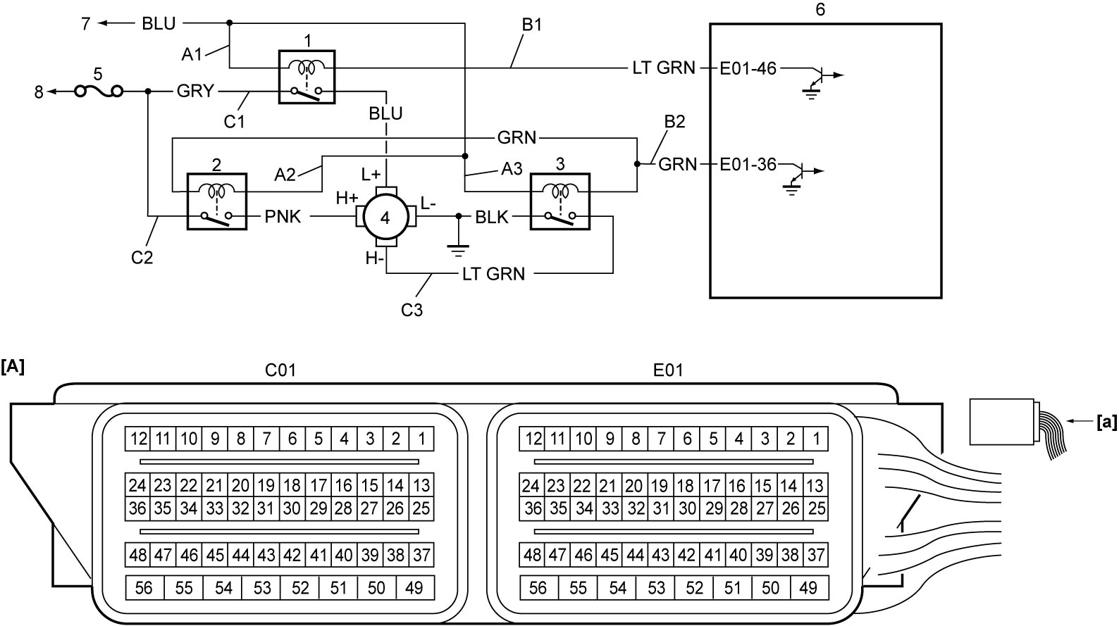
| [A]: | ECM connector (View: [a]) | C1: | Radiator cooling fan relay No.1 power supply circuit (switch side) | 4. | Radiator cooling fan motor |
| A1: | Radiator cooling fan relay No.1 power supply circuit (coil side) | C2: | Radiator cooling fan relay No.2 power supply circuit (switch side) | 5. | “RDTR” fuse |
| A2: | Radiator cooling fan relay No.2 power supply circuit (coil side) | C3: | Radiator cooling fan relay No.3 power supply circuit (switch side) | 6. | ECM |
| A3: | Radiator cooling fan relay No.3 power supply circuit (coil side) | 1. | Radiator cooling fan relay No.1 | 7. | To main relay |
| B1: | Radiator cooling fan relay No.1 drive circuit | 2. | Radiator cooling fan relay No.2 | 8. | To main fuse box |
| B2: | Radiator cooling fan relay No.2 and No.3 drive circuit | 3. | Radiator cooling fan relay No.3 |
DTC Confirmation Procedure
NOTE:
Check that the following condition is met in this “DTC Confirmation Procedure”.
•Battery voltage > 8.5 V
1)Warm up engine to normal operating temperature.
2)Keep engine at idle speed until engine coolant temperature reaches 100 °C (212 °F) or more.
DTC Troubleshooting
| Step | Action | Yes | No |
|---|---|---|---|
| 1 |
Was “Engine and Emission Control System Check” performed?
|
Go to Step 2.
|
|
| 2 |
Radiator cooling fan relay No.1 power supply circuit (coil side) check
1)With ignition “OFF”, remove radiator cooling fan relay No.1.
2)Check for proper terminal connection to radiator cooling fan relay No.1 connector.
3)If connection is OK, set ignition “ON”.
4)Check that voltage between “A1” and ground is battery voltage.
Is check result OK?
|
Go to Step 3.
|
Repair or replace defective wire harness.
|
| 3 |
Radiator cooling fan relay No.1 check
1)Check radiator cooling fan relay No.1.

Is check result OK?
|
Go to Step 4.
|
Replace radiator cooling fan relay No.1.
|
| 4 |
Radiator cooling fan relay No.1 drive circuit check
1)With ignition “OFF”, disconnect “C01” and “E01” connectors from ECM.
2)Check for proper terminal connection to “C01” and “E01” connectors.
3)If connections are OK, check the following points.
•Resistance of “B1” circuit: less than 1 Ω
•Resistance between “B1” circuit and ground: infinity •Resistance between “B1” circuit terminal and other terminal at radiator cooling fan relay No.1 connector: infinity •Voltage of “B1” circuit: approx. 0 V (When ignition is “ON”) Is check result OK?
|
Replace ECM and recheck DTC.
|
Repair or replace defective wire harness.
|