DTC P0A5A
Precautions: General safety (00)
DTC Detecting Condition and Trouble Area
| DTC detecting condition | Trouble area |
|---|---|
|
P0A5A: Generator Current Sensor Circuit Range / Performance Any of the following conditions is met.
•Output voltage of electric load current sensor signal circuit is more than 4.80 V for 5 sec. (3 D/C detection logic but MIL does not light up)•Output voltage of electric load current sensor signal circuit is lower than 0.20 V for 5 sec. •Output voltage of electric load current sensor signal circuit fluctuates less than specified value for 5 sec. |
•Electric load current sensor and/or its circuit
•ECM •ENG A-STOP control module |
Circuit Diagram
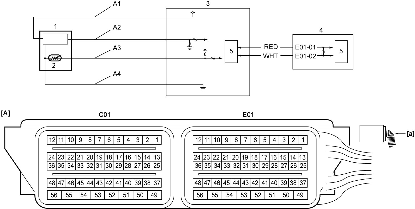
| [A]: | ECM connector (View: [a]) | A4: | Electric load current sensor ground circuit | 4. | ECM |
| A1: | Electric load current sensor power supply circuit | 1. | Electric load current sensor | 5. | CAN driver |
| A2: | Electric load current sensor signal circuit | 2. | Battery temperature sensor | ||
| A3: | Battery temperature sensor signal circuit | 3. | ENG A-STOP control module |
DTC Confirmation Procedure
1)Set ignition “ON” for 10 sec.
2)Start engine at idle speed for 10 min.
DTC Troubleshooting
| Step | Action | Yes | No |
|---|---|---|---|
| 1 |
Was “Engine and Emission Control System Check” performed?
|
Go to Step 2.
|
|
| 2 |
DTC check
1)Check DTC in ENG A-STOP control module.

Is DTC P1321 or P1322 still detected?
|
Go to DTC P1321 / P1322.
|
Go to Step 3.
|
| 3 |
DTC check
Is there any DTC(s) other than P1321 and P1322?
|
Go to troubleshooting for applicable DTC.
|
Go to Step 4.
|
| 4 |
Electric load current sensor signal circuit check
1)Check “A1”, “A2” and “A4” circuits according to Step 1 – 4 under DTC P1321 / P1322.
Is check result OK?
|
Go to Step 5.
|
Repair or replace defective wire harness.
|
| 5 |
Electric load current sensor check
1)Check electric load current sensor.
Is check result OK?
|
Replace ECM and recheck DTC.
|
Replace electric load current sensor.
|