A/F Sensor-1 Check
Precautions: General safety (00)
Circuit Diagram
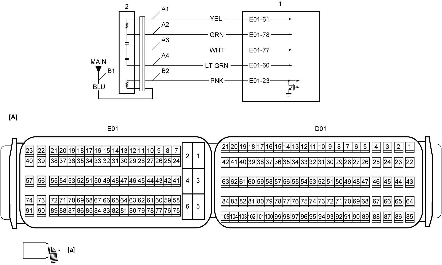
| [A]: | ECM connector (View: [a]) | A3: | A/F sensor-1 signal circuit (IPN) | B2: | A/F sensor-1 heater drive circuit |
| A1: | A/F sensor-1 signal circuit (RT) | A4: | A/F sensor-1 signal circuit (RE+) | 1. | ECM |
| A2: | A/F sensor-1 signal circuit (APE) | B1: | A/F sensor-1 heater power supply circuit | 2. | A/F sensor-1 |
Troubleshooting
| Step | Action | Yes | No |
|---|---|---|---|
| 1 |
A/F sensor-1 heater power supply circuit check
1)When ignition is “OFF”, disconnect A/F sensor-1 connector.
2)Check for proper terminal connection to A/F sensor-1 connector.
3)If connections are OK, set ignition “ON”.
4)Check that voltage between “B1” circuit and ground is battery voltage.
Is check result OK?
|
Go to Step 2.
|
Repair or replace defective wire harness.
|
| 2 |
A/F sensor-1 heater drive circuit check
1)When ignition is “OFF”, disconnect “E01” connector from ECM.
2)Check for proper terminal connection to “E01” connector.
3)If connections are OK, check the following points.
•Resistance of “B2” circuit: less than 1 Ω
•Resistance between “B2” circuit and ground: infinity •Resistance between “B2” circuit terminal and other terminal at A/F sensor-1 connector: infinity •Voltage of “B2” circuit: approx. 0 V (When ignition is “ON”) Is check result OK?
|
Go to Step 3.
|
Repair or replace defective wire harness.
|
| 3 |
A/F sensor-1 signal circuit check
1)Check the following points.
•Resistance of “A1, “A2”, “A3” and “A4” circuits: less than 1 Ω
•Resistance between each of “A1, “A2”, “A3” and “A4” circuits and ground: infinity •Resistance between “A1” circuit terminal and other terminal at A/F sensor-1 connector: infinity •Resistance between “A2” circuit terminal and other terminal at A/F sensor-1 connector: infinity •Resistance between “A3” circuit terminal and other terminal at A/F sensor-1 connector: infinity •Resistance between “A4” circuit terminal and other terminal at A/F sensor-1 connector: infinity •Voltage of “A1, “A2”, “A3” and “A4” circuits: approx. 0 V (When ignition is “ON”) Is check result OK?
|
Go to Step 4.
|
Repair or replace defective wire harness.
|
| 4 |
A/F sensor-1 check
1)Check A/F sensor-1.

Is check result OK?
|
End.
|
Replace A/F sensor-1.
|