Radiator Cooling Fan Control System Circuit Diagram
Precautions: Precautions for Cooling System · General safety (00)
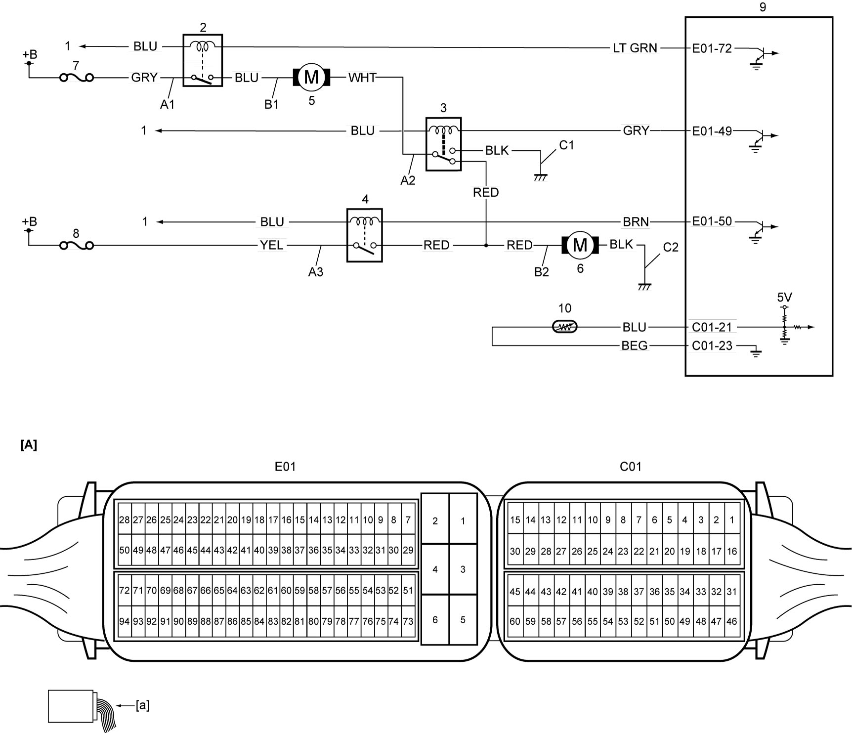
| [A]: | ECM connector (View: [a]) | C1: | Radiator cooling fan relay No.2 ground circuit | 5. | Radiator cooling main fan motor |
| A1: | Radiator cooling fan relay No.1 power supply circuit (switch side) | C2: | Radiator cooling sub fan motor ground circuit | 6. | Radiator cooling sub fan motor |
| A2: | Radiator cooling fan relay No.2 power supply circuit (switch side) | 1. | To main relay | 7. | “RDTR” fuse |
| A3: | Radiator cooling fan relay No.3 power supply circuit (switch side) | 2. | Radiator cooling fan relay No.1 | 8. | “RDTR2” fuse |
| B1: | Radiator cooling main fan motor drive circuit | 3. | Radiator cooling fan relay No.2 | 9. | ECM |
| B2: | Radiator cooling sub fan motor drive circuit | 4. | Radiator cooling fan relay No.3 | 10. | ECT sensor |