Fuel Hose Disconnection and Reconnection
Precautions: Precautions for Fuel System Service · General safety (00)
Before performing the following procedure, observe Precautions for Fuel System Service:K14C.
Non-Quick Joint Connections
Clamp around fuel tank
NOTE:
•Install hose in the raised part of pipe securely.
•Fit the clamp so that the center between both ends of the clamp (8) or the center of the screw thread of the clamp (9) is positioned in range “d” shown in figure below.
•The clamp (4) screw position in figure below is for service work, but the positioning is upside down at the factory.
•Fit the clamp so that the center between both ends of the clamp (8) or the center of the screw thread of the clamp (9) is positioned in range “d” shown in figure below.
•The clamp (4) screw position in figure below is for service work, but the positioning is upside down at the factory.
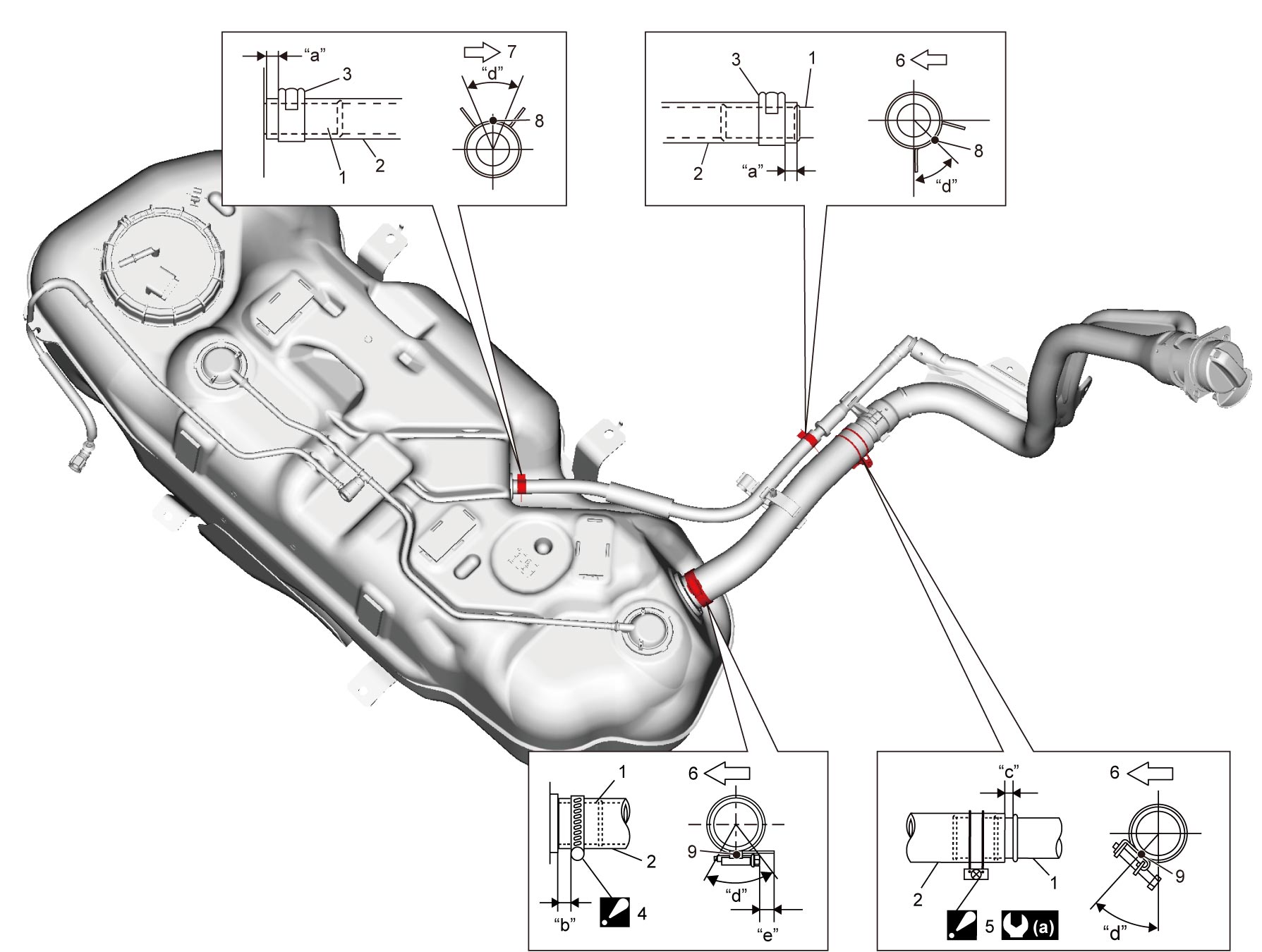
| “a”: | 3 – 7 mm (0.12 – 0.27 in.) | 1. | Pipe | 6. | Vehicle leftward |
| “b”: | 5 – 10 mm (0.20 – 0.39 in.) | 2. | Hose | 7. | Vehicle rightward |
| “c”: | 0 – 8 mm (0 – 0.31 in.) | 3. | Clamp |
|
1.5 N·m (0.15 kgf-m, 1.5 lbf-ft) |
| “d”: | 45° |
|
Fuel tank filler hose clamp : For installation, refer to Fuel Tank Filler Hose. |
||
| “e”: | 13 – 17 mm (0.51 – 0.67 in.) |
|
Fuel tank filler clamp : For installation, refer to Fuel Tank Filler Hose. |
Fuel Tank Filler Hose
Disconnection
1)Remove fuel filler cap.
2)Insert hose of hand operated pump into fuel tank through fuel filler neck.
NOTICE:
The hose of the hand operated pump could damage the fuel tank inlet valve if excessive force is applied when inserting or removing it to or from the fuel tank.
Do not apply excessive force when inserting or removing the hose of the hand operated pump.
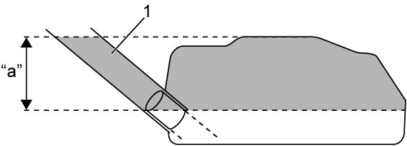
3)Pump out fuel in space “a” shown in figure.
 WARNING:

WARNING:
There is a risk of fire or explosion due to static electricity if the drained fuel is stored in an open container or plastic container.
Store the fuel in a sealed metal container.
| 1. | Fuel tank filler hose |
4)Remove hose of hand operated pump from fuel filler neck.
5)Hoist vehicle.
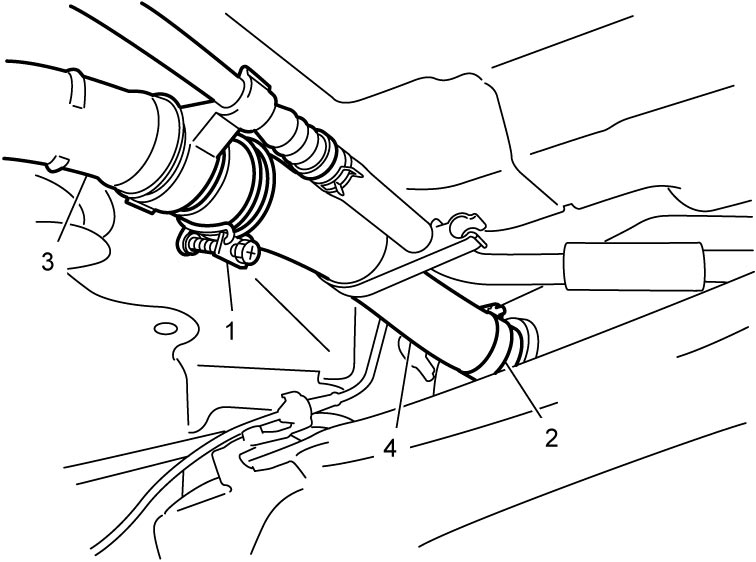
6)Loosen fuel tank filler clamp (1) and fuel tank filler hose clamp (2).
7)Disconnect fuel tank filler hose (4) at fuel filler neck while temporarily placing a fuel tank filler clamp on fuel filler neck (3).
8)Remove fuel tank filler hose along with fuel tank filler hose clamp.
Reconnection
1)Temporarily fit fuel tank filler hose clamp to fuel tank filler hose.
2)Install fuel tank filler hose (1) to fuel tank (2).
NOTE:
Install the fuel tank filler hose with identification marks on the hose end facing up (approximately).
3)Position fuel tank filler hose clamp (3) as specified.
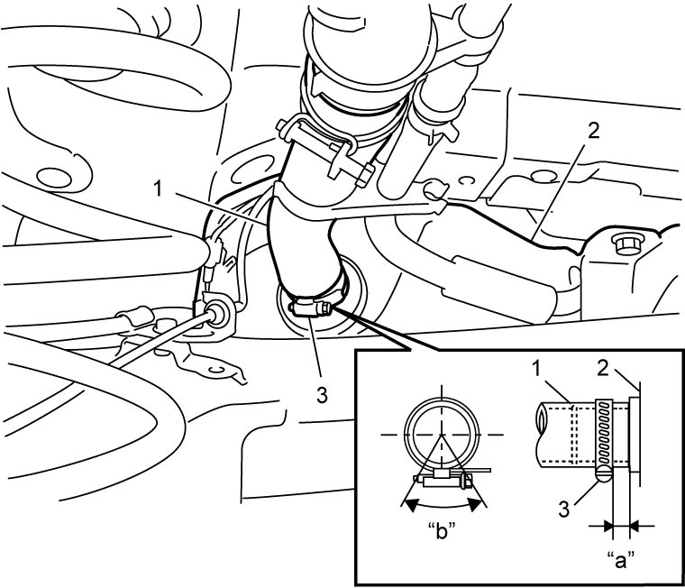
Clearance between fuel tank and fuel tank filler hose clamp
“a”: 5 – 10 mm (0.20 – 0.39 in.)
Position of clamp screw mid-point within range
“b”: 45 °
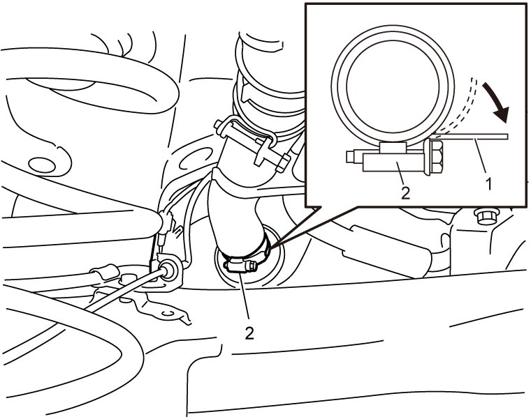
4)Pull band part (1) of fuel tank filler hose clamp in arrow direction with finger so that it is placed in parallel to the bolt part (2).
5)Tighten fuel tank filler hose clamp (1) until length “a” reaches specified value.
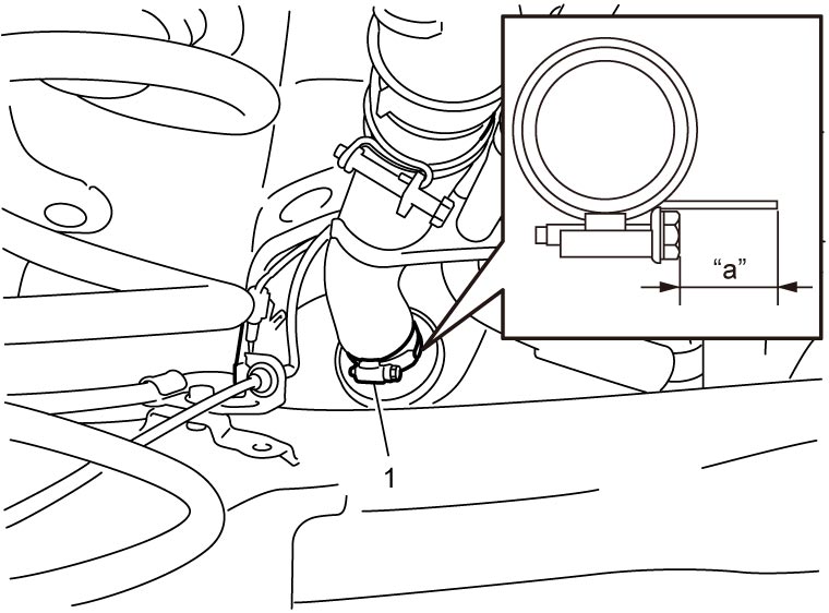
Protruding length of band part of clamp
“a”: 13 – 17 mm (0.51 – 0.67 in.)
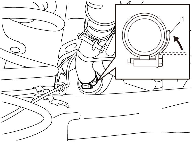
6)Push band part (1) in arrow direction with finger and put it back.
7)Apply fuel to all around the outer circumference of fuel tank filler hose attachment section of the fuel filler neck.
NOTICE:
Remaining lint from cloth may cause fuel leakage.
Use lint-free cloth to apply fuel.
NOTE:
Apply fuel to insert fuel tank filler hose into proper position.
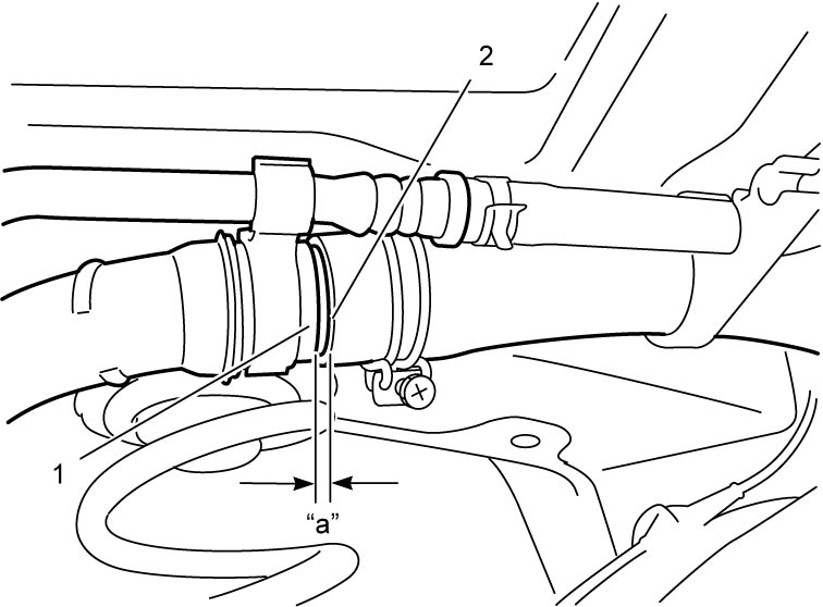
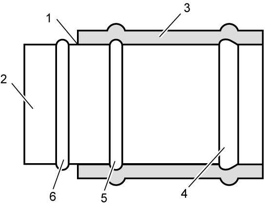
8)Insert fuel tank filler hose (1) to fuel filler neck as far as the hose end reaches the 2nd spool (3) on fuel filler neck (2).
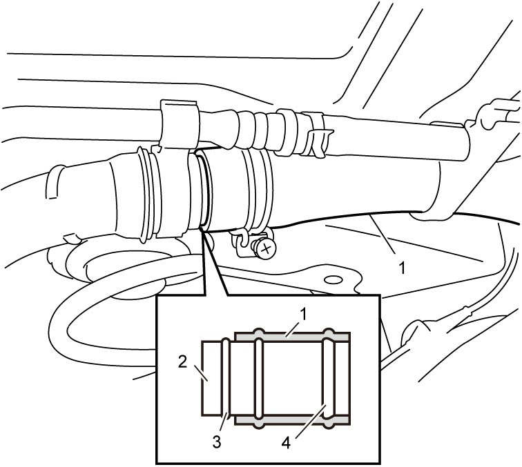
| 4. | Bulge |
9)Release hand and check that there is a clearance “a” between the 2nd spool (1) and fuel tank filler hose end (2).
 Fuel tank filler hose end position not OK
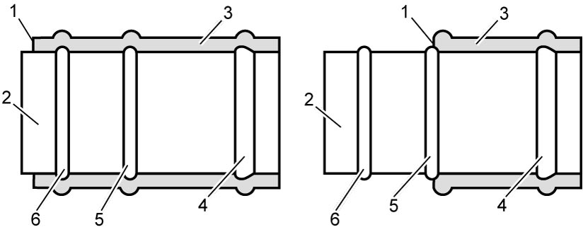
Clearance between 2nd spool and fuel filler hose end
“a”: 0 – 8 mm (0 – 0.31 in.)
NOTE:
Fuel tank filler hose end position OKRefer to the following illustration for fuel tank filler hose positioning.
| 1. | Hose end position | 4. | Bulge |
| 2. | Fuel filler neck | 5. | 1st spool |
| 3. | Fuel filler hose | 6. | 2nd spool |
10)Install clamp (1) of fuel filler neck side just between the 1st spool and bulge (arrow portions) on the fuel tank filler hose.
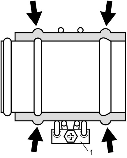
11)Hold fuel tank filler clamp straight by hand at the center between the 1st spool and bulge and specified angle.
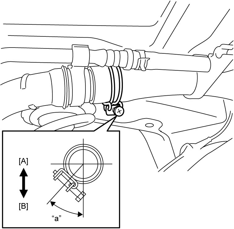
Position range for center of clamp screw thread
“a”: 45 °
| [A]: | Upper side | [B]: | Lower side |
12)Tighten fuel tank filler clamp to specified torque.
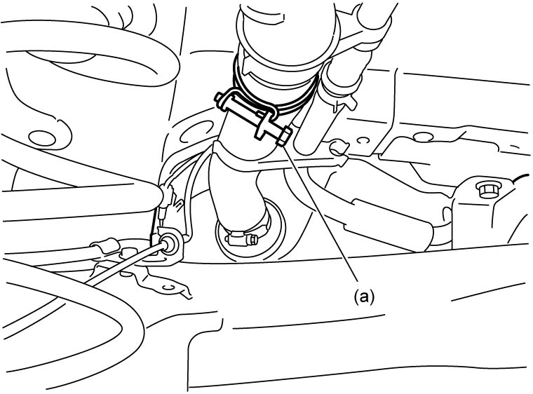
13)Visually check bulge on fuel tank filler hose. Repeat Step 7) – 12) if check result is not as specified.
Fuel tank filler hose bulge is in good shape
Bulge “A” = “B”: In uniform contact with pipe
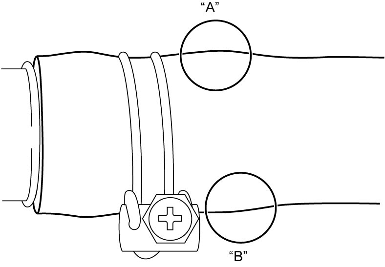 Fuel tank filler hose bulge is not in good shape
Bulge “C”: In excess contact with pipe
Bulge “D”: In poor contact with pipe
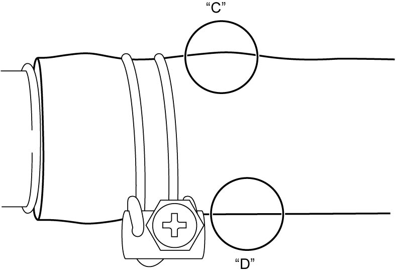
Fuel tank filler hose bulge is in good shape
Bulge “A” = “B”: In uniform contact with pipe
Bulge “C”: In excess contact with pipe
Bulge “D”: In poor contact with pipe
14)Connect plastic clamp to fuel filler hose.
15)Lower vehicle.
16)If fuel is drained, return fuel to fuel tank.
17)Install fuel filler cap.
Clamp other than around fuel tank
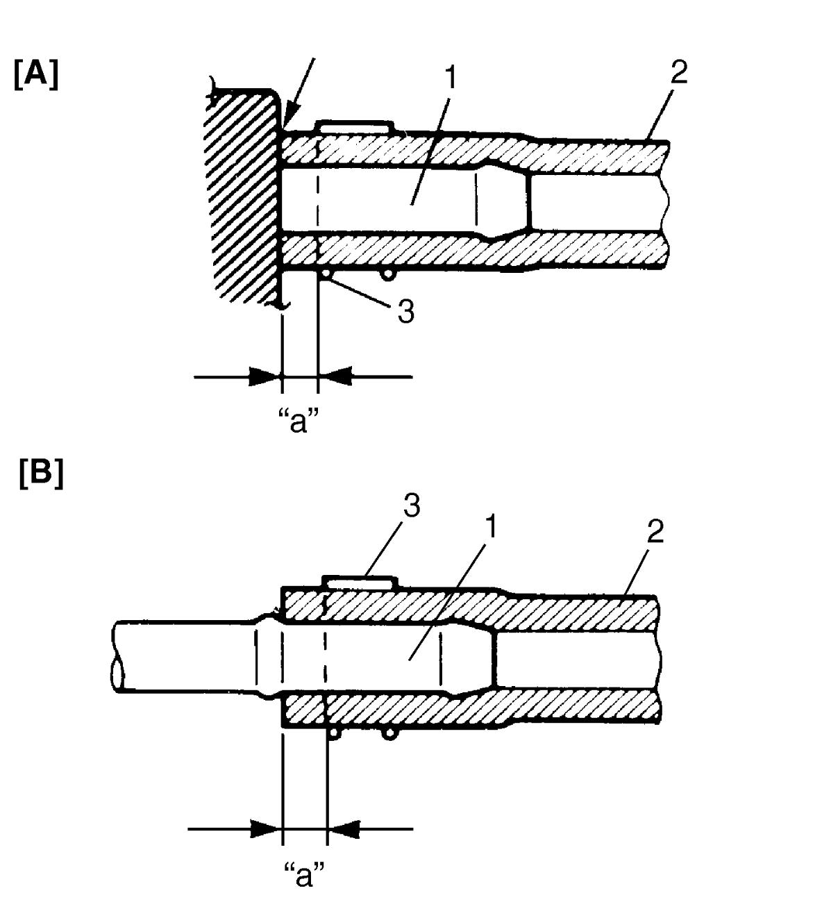
| [A]: | With short pipe, fit hose as far as it reaches the end of pipe joint as shown. | 1. | Pipe |
| [B]: | With the above type pipe, fit hose as far as it reaches bulge on fuel pipe. | 2. | Hose |
| “a”: | 3 – 7 mm (0.12 – 0.28 in.) | 3. | Clamp |
Quick Joint Connections
Disconnection
1)Remove mud, dust and/or foreign material between pipe (1) and quick joint (2) using compressed air.
2)Disconnect quick joint from fuel pipe while pushing lock button (3) on joint.
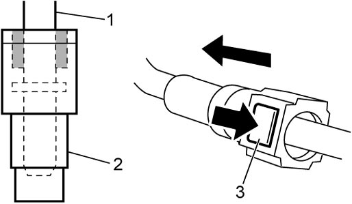
Reconnection
Insert quick joint to fuel pipe until they lock securely (a click is heard), and check that quick joint is not disconnected by hand.