Starting Motor Disassembly and Reassembly (Non-ENG A-STOP Model)
Precautions: General safety (00)
NOTE:
Disassembly of starting motor for ENG A-STOP model is not specified. Therefore, if any faulty condition is found, replace the starting motor with a new one. 
Disassembly
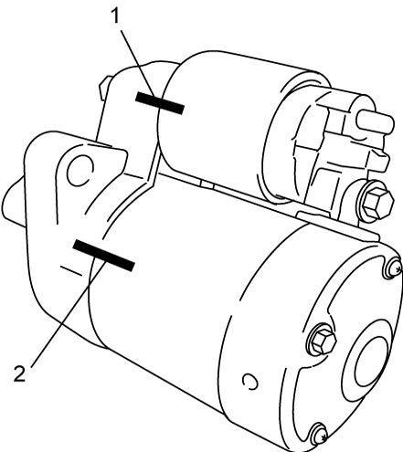
1)Before disassembly, draw matchmarks (1) and (2) as shown in figure to assure proper alignment when reassembled.

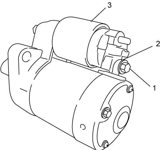
2)Remove nut (1) and disconnect lead wire (2) from magnetic switch (3).
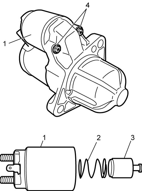
3)Remove screws (4) and pull out magnetic switch (1) from starting motor assembly.
4)Remove spring (2) and plunger (3) from magnetic switch body.
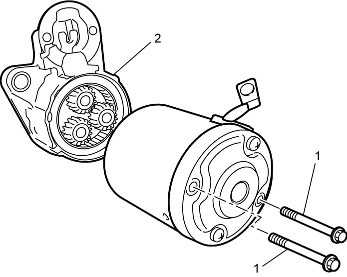
5)Remove bolts (1) and separate yoke from armature housing (2).
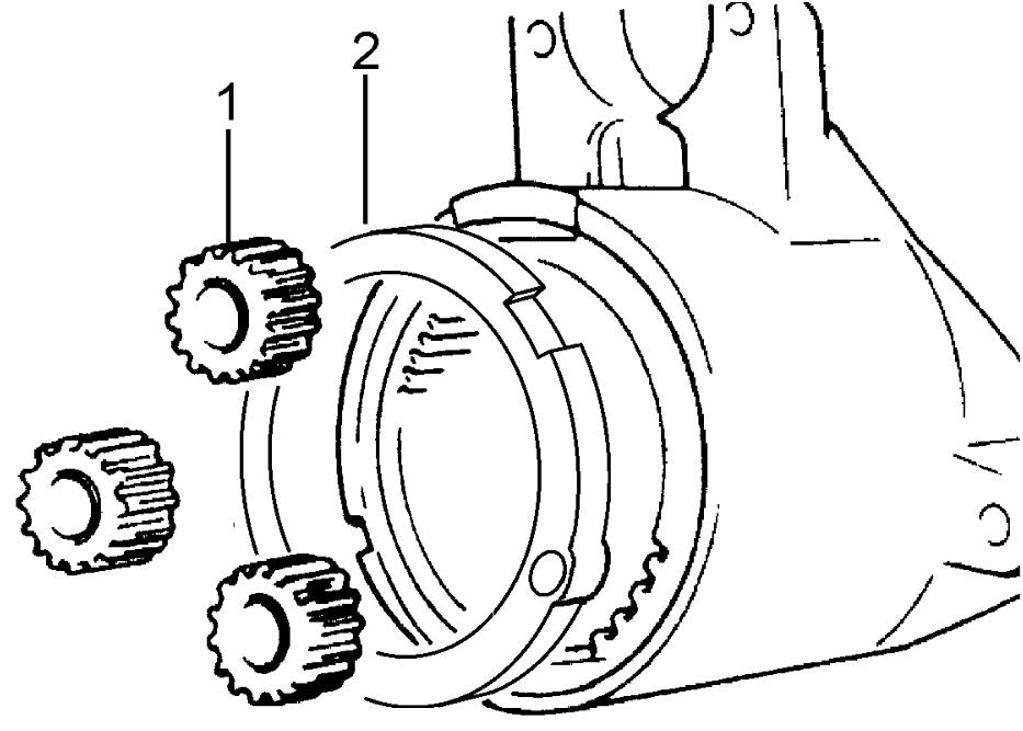
6)Remove grommet (2) and planetary gears (1).
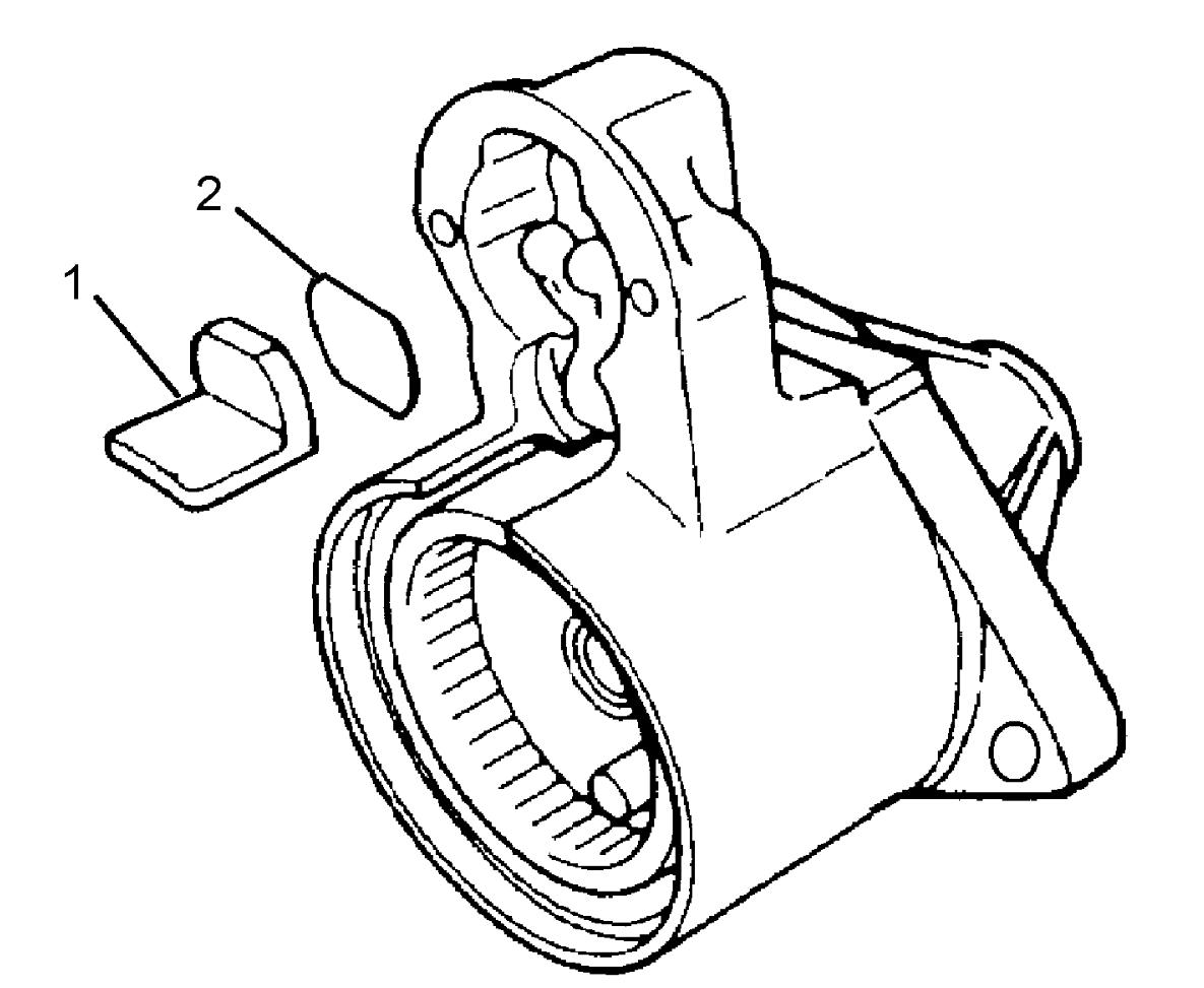
7)Remove seal rubber (1) and plate (2).
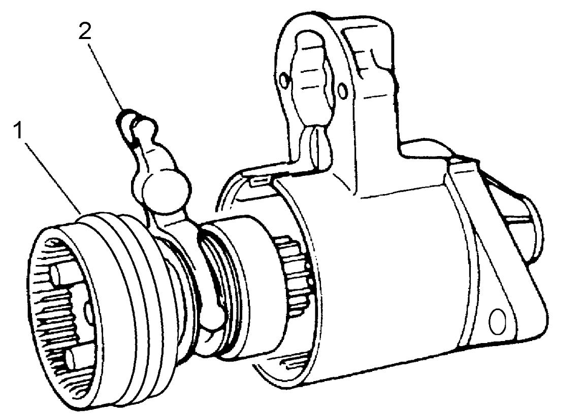
8)Remove shaft assembly (1) together with drive lever (2).
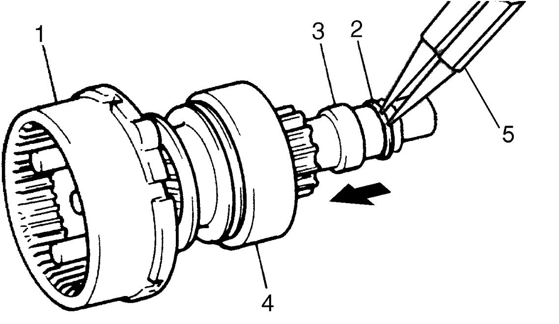
9)With pinion stop ring (3) moved toward overrunning clutch (4) side (in arrow direction), remove snap ring (2) using snap ring pliers (5).
10)Remove pinion stop ring (3), overrunning clutch (4) and internal gear (1) from gear shaft.
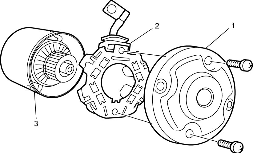
11)Remove end housing (1) and remove brush assembly (2) from yoke (3).
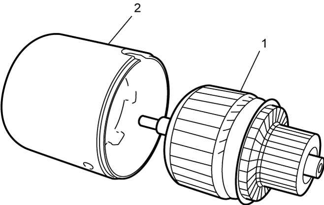
12)Remove armature (1) from yoke (2).
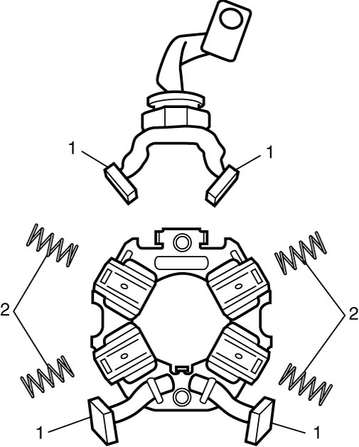
13)Remove brushes (1) and brush springs (2).
Reassembly
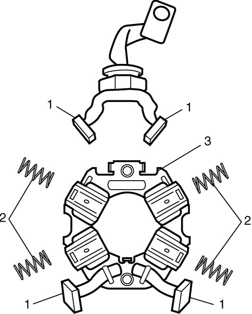
1)Install brush springs (2) and brushes (1) to brush holder (3).
2)Install armature (2) to yoke.
3)Install brush assembly (1) to armature (2) while pushing 4 brushes (3) outward.

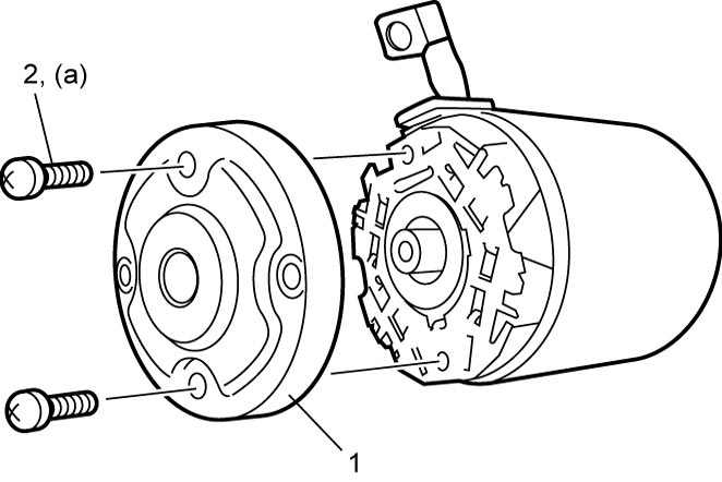
4)Install end housing (1) to brush holder and tighten brush holder screws (2) to specified torque.
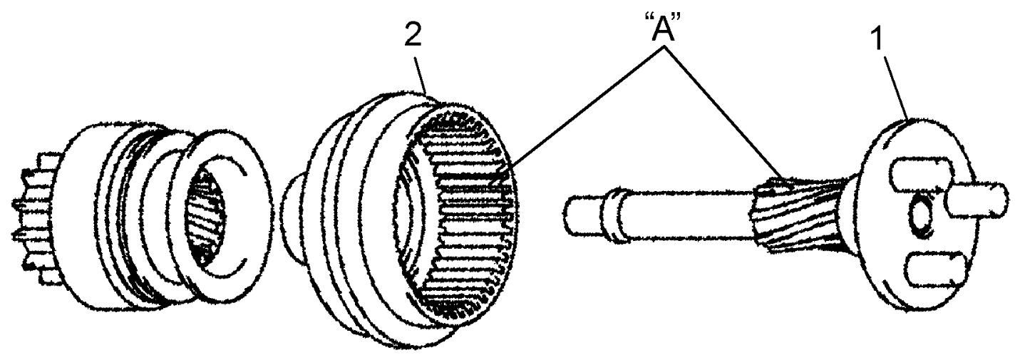
5)Apply grease to spline of gear shaft (1) and teeth of internal gear (2).
6)Install internal gear and overrunning clutch (1) to gear shaft (4) using new snap ring (3) and pinion stop ring (2).
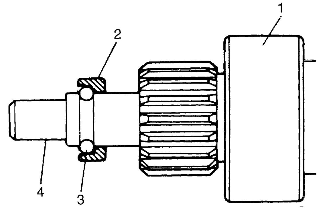
NOTE:
Install pinion stop ring in the direction and position as shown in figure.
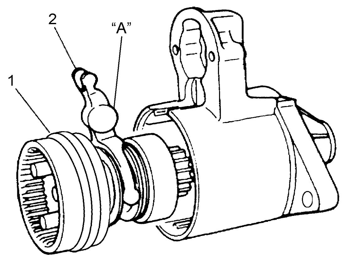
7)Apply grease to drive lever (2) and insert shaft assembly (1) into armature housing with drive lever positioned as shown in figure.
8)With armature housing bolt holes (3) and cutouts in grommet aligned, install grommet (1) in armature housing.
9)Install plate (5) and seal rubber (4) to armature housing.
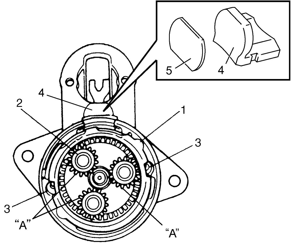
10)Apply grease to planetary gears (2) and install planetary gears to gear shaft.
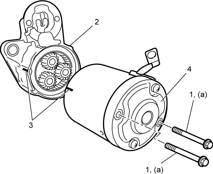
11)Install yoke, armature, brush assembly and end housing (4) to armature housing (2) while aligning matchmarks (3) drawn before disassembly.
12)Tighten end housing bolts (1) to specified torque.
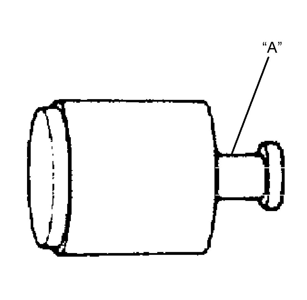
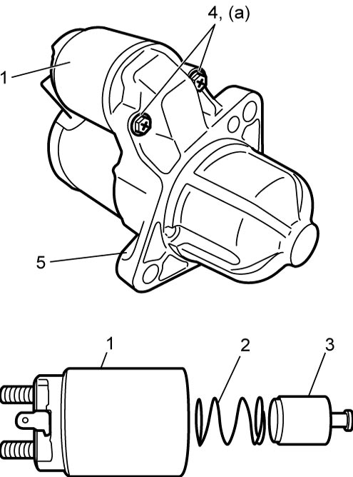
14)Install magnetic switch (1), spring (2) and plunger (3) to armature housing (5) while aligning matchmarks drawn before removal.
15)Tighten screws (4) to specified torque.
16)Connect lead wire (1) to terminal “M” (2) and tighten lead wire nut to specified torque.
17)Check magnetic switch for operation.