Starting Motor Disassembly and Reassembly
Precautions: General safety (00)
Disassembly
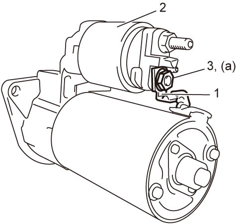
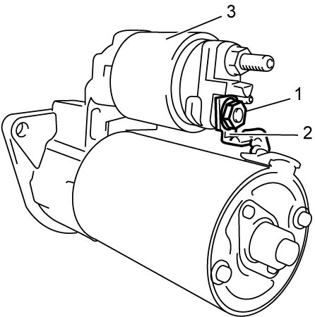
1)Remove nut (1) and disconnect lead wire (2) from magnetic switch (3).

2)Remove bolts (1), and then remove magnetic switch (2).
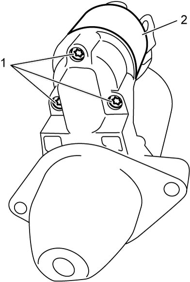
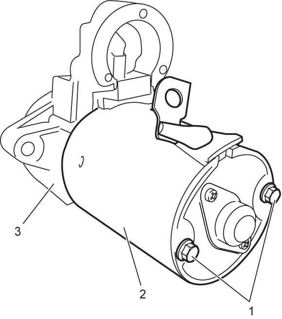
3)Remove bolts (1), and then separate yoke (2) from starter housing (3).
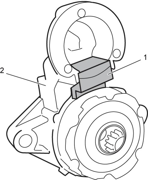
4)Remove seal rubber (1) from starter housing (2).
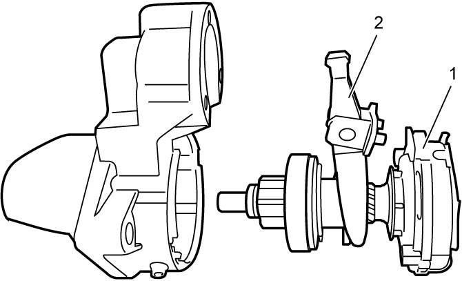
5)Remove gear shaft (1) together with drive lever (2).
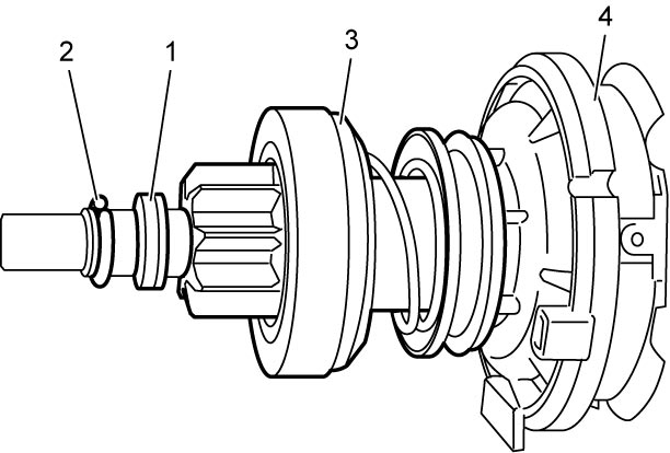
6)Pull retainer (1) toward overrunning clutch (3) and remove stop ring (2).
7)Remove retainer (1) and overrunning clutch (3) from gear shaft (4).
8)Remove armature (1), brush assembly (2) and starter end frame (3) from yoke (4).
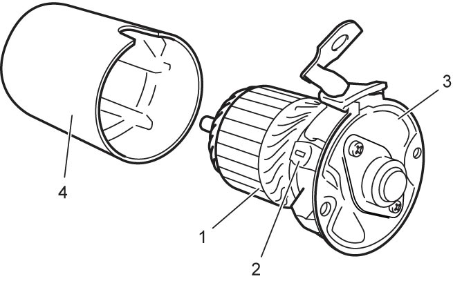
9)Remove screws (1), and then remove closure cap (2).
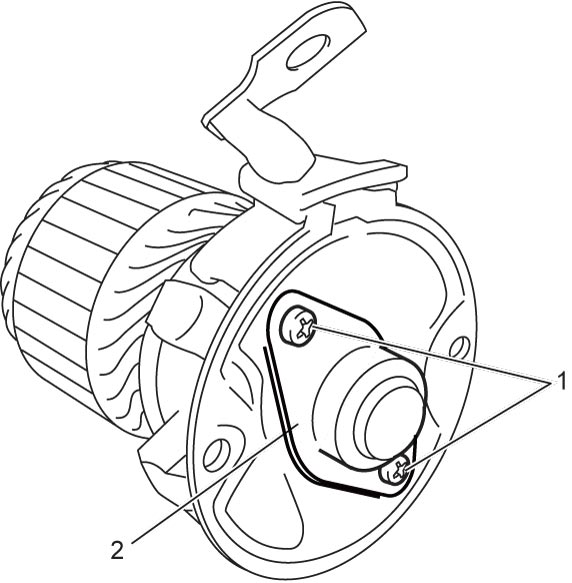
10)Remove retaining washer (1) and shim (2), and then remove starter end frame (3).
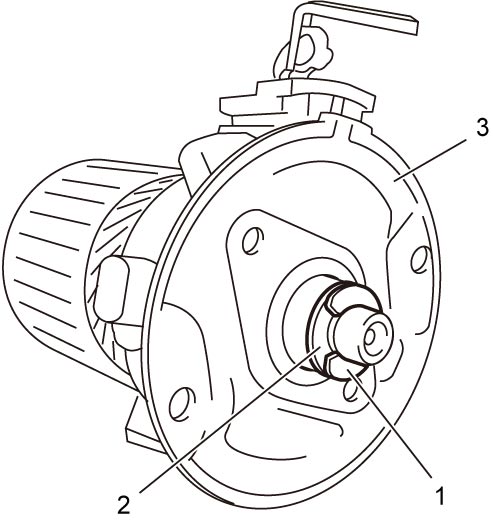
11)Remove brush (1) from armature (2).
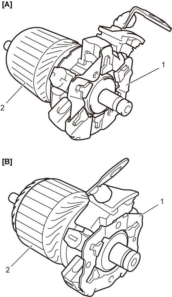
| [A]: | ENG A-STOP model | [B]: | Non-ENG A-STOP model |
Reassembly
1)Install brush assembly (1) to armature (2) while pushing 6 brushes (ENG A-STOP model) or 4 brushes (Non-ENG A-STOP model) (3) outward.
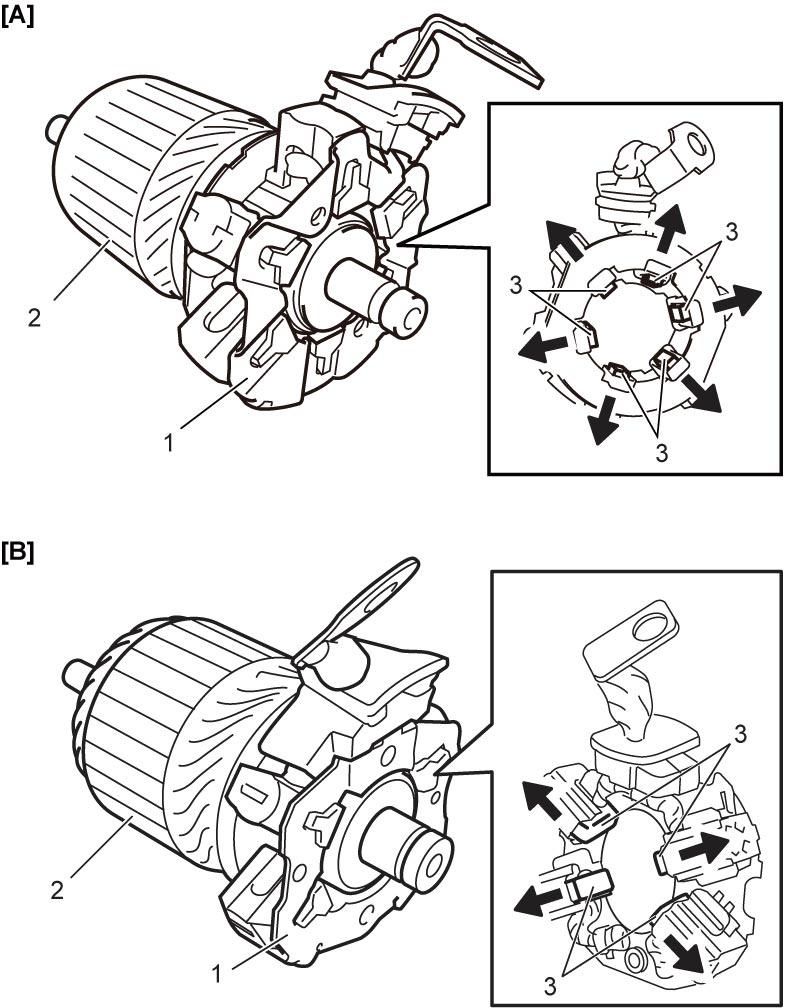
| [A]: | ENG A-STOP model | [B]: | Non-ENG A-STOP model |
2)Install starter end frame (3), shim (2) and retaining washer (1).
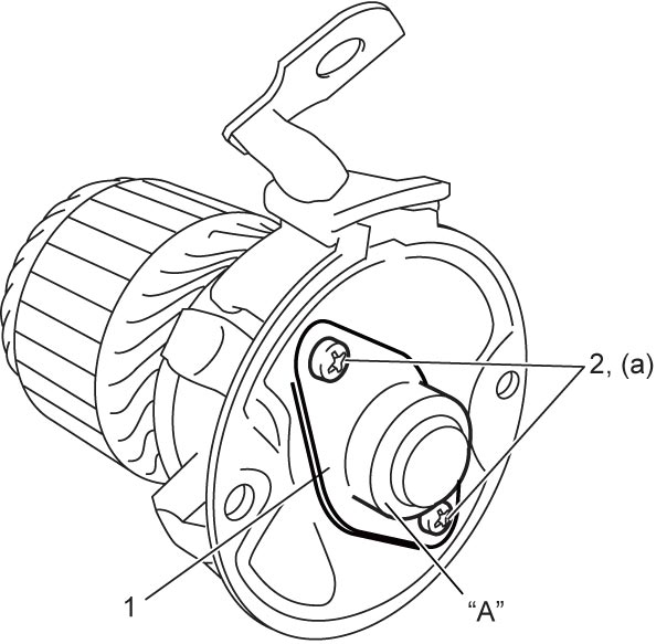
4)Install closure cap (1), and then tighten closure cap screws (2) to specified torque.
5)Install armature (1), brush (2) and starter end frame (3) to yoke (4).
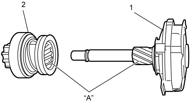
6)Before installing overrunning clutch (2) to gear shaft (1), apply grease to splines.
7)Install overrunning clutch (1) to gear shaft (4) with new retainer (2) and stop ring (3).
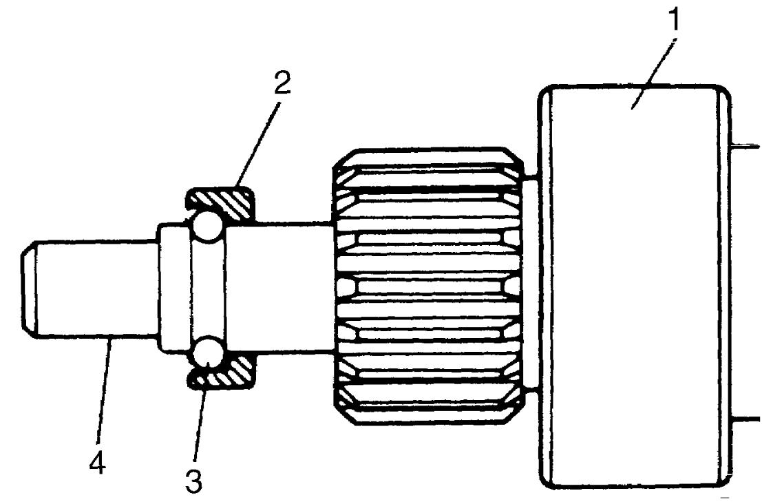
NOTE:
Install stop ring in the direction and position as shown in figure.
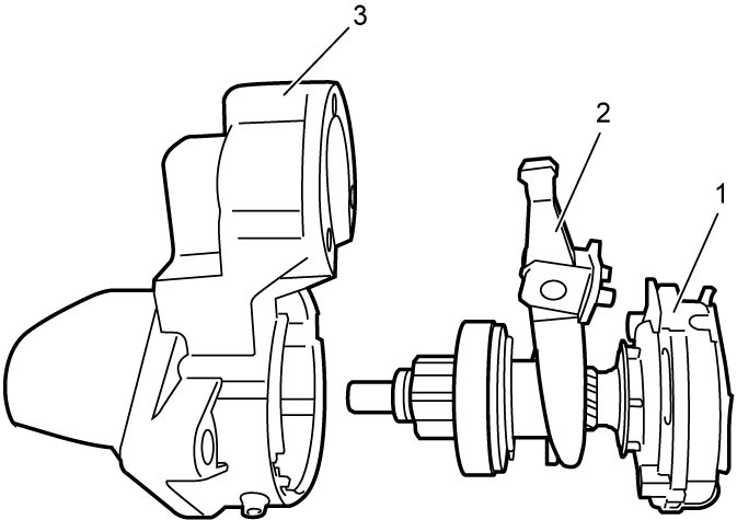
8)Insert gear shaft (1) into starter housing (3) with drive lever (2) positioned as shown in figure.
9)Install seal rubber (1) to starter housing (2).
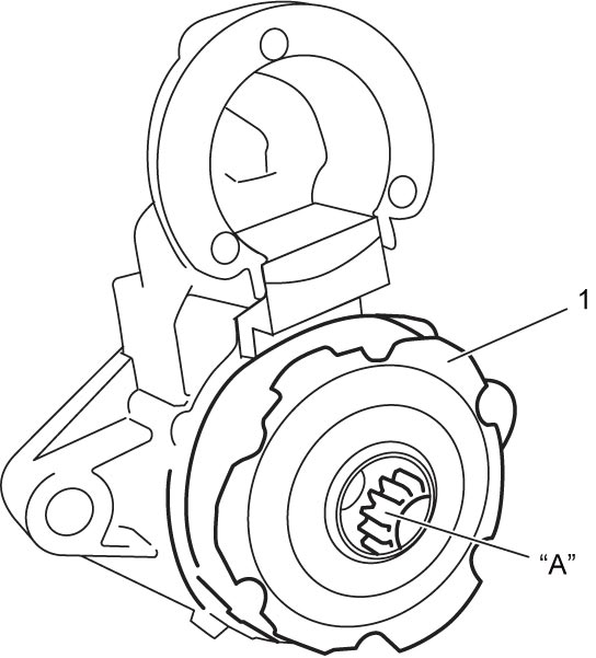
10)Before installing yoke to starter housing, apply grease to gears of gear shaft (1).
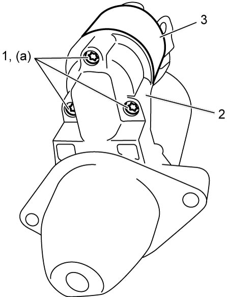
11)Install yoke (2) to starter housing (3), and then tighten starter end frame bolts (1) to specified torque.
Starter end frame bolt (a): 4.8 N·m (0.49 kgf-m, 3.5 lbf-ft)(ENG A-STOP model)
Tightening torque
Starter end frame bolt (a): 7.5 N·m (0.76 kgf-m, 5.5 lbf-ft)(Non-ENG A-STOP model)Starter end frame bolt (a): 4.8 N·m (0.49 kgf-m, 3.5 lbf-ft)(ENG A-STOP model)
12)Install magnetic switch (3) to starter housing (2), and then tighten new magnetic switch bolts (1) to specified torque.