Generator Disassembly and Reassembly
Precautions: Precautions for Handling Battery · Precautions for Replacing Battery · General safety (00)
Disassembly
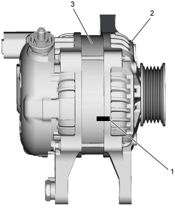
1)To facilitate reinstallation, provide matchmarks (1) on drive end frame (2) and stator (3) as shown.

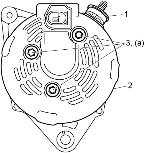
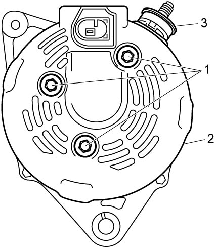
2)Remove rear end cover bolts (1), and then remove rear end cover (2) from stator assembly.
3)Remove bushing (3) from “B” terminal.
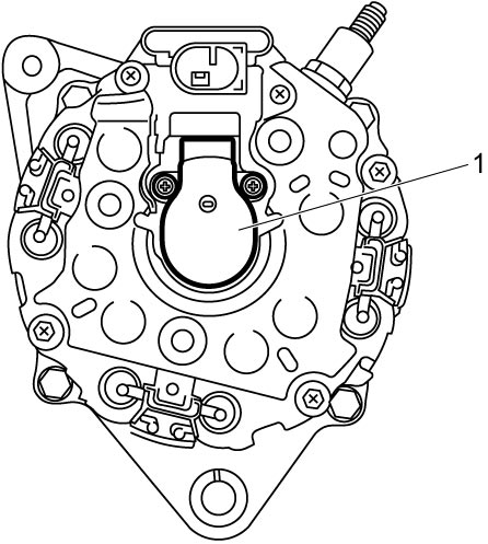
4)Remove brush holder assembly (1) from stator assembly.
5)Hold shaft using hexagonal box wrench (1), remove pulley nut, and then pull out pulley (2).
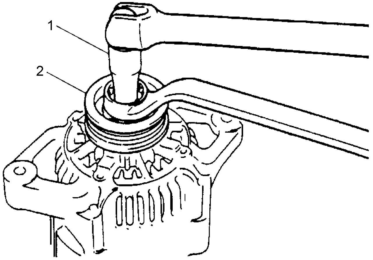
NOTICE:
The shaft end is not hard enough and the end may be damaged if it is held using a 12-point socket wrench.
Do not use 12-point socket wrench to hold the shaft.
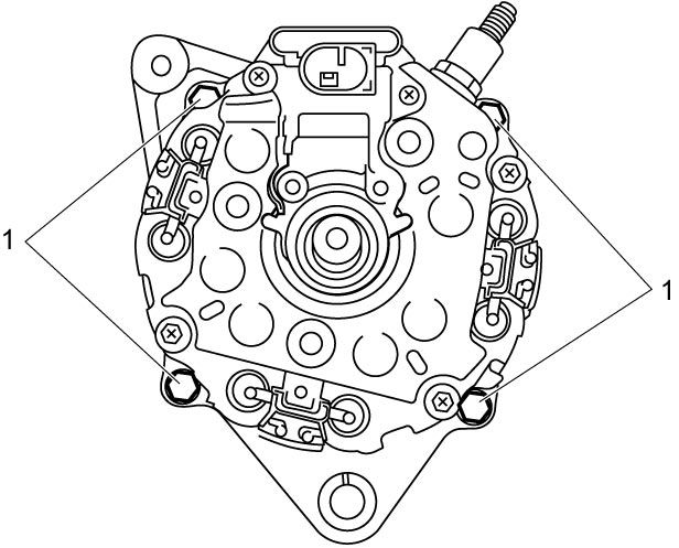
6)Remove stator assembly bolts (1).
7)Remove stator assembly (1) with rotor from drive end frame (2) by tapping shaft (3) lightly using plastic hammer.
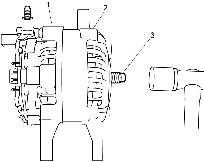
8)Remove stator assembly from rotor by tapping stator assembly evenly using plastic hammer.
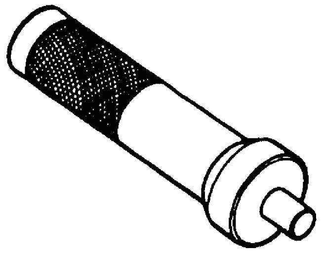
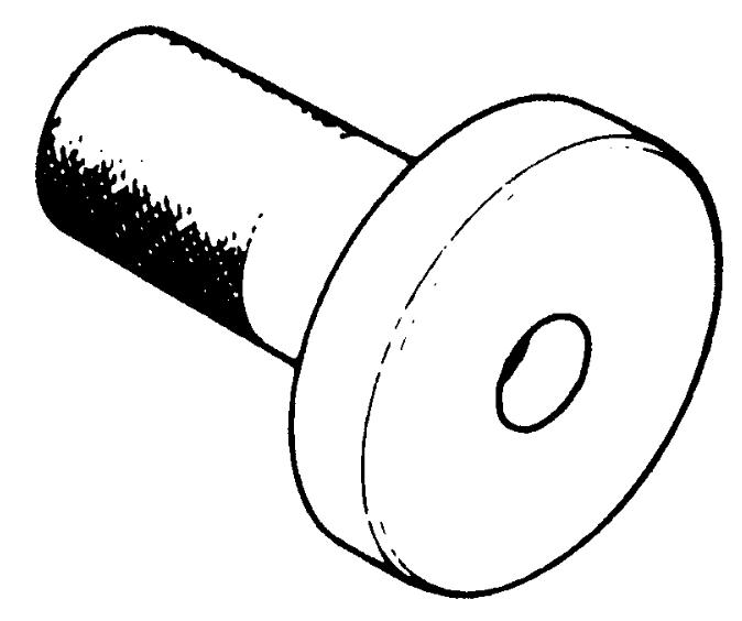
9)If necessary, remove bearing retainer screws and bearing retainer (1), and then remove bearing (2) from drive end frame (3) using special tool.
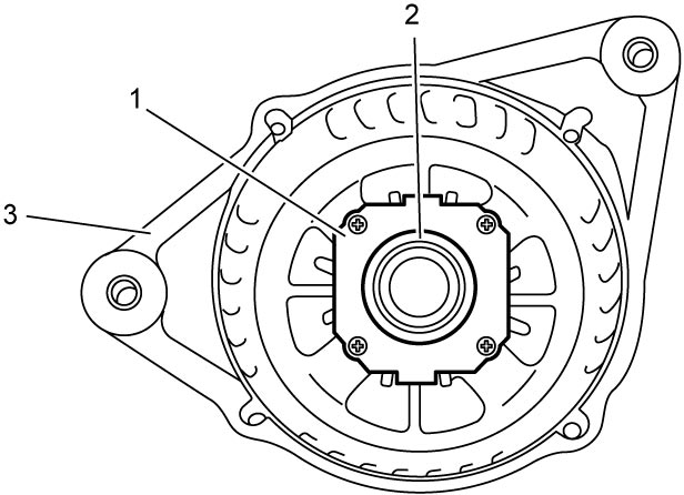
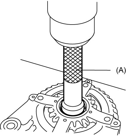
NOTE:
If necessary, heat drive end frame to a temperature of 80 – 100 °C (176 – 212 °F) so that it will not be distorted, and remove bearing.
Reassembly
1)Using special tool, install new bearing to drive end frame, and check the bearing for smooth rotation, if removed.
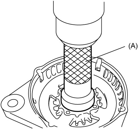
NOTICE:
When installing the bearing, the bearing and the drive end frame may become damaged if pressing any section other than the outer race.
Press the outer race of the bearing when installing it.
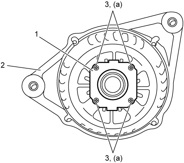
2)Install bearing retainer (1) to drive end frame (2), and then tighten bearing retainer screws (3) to specified torque.
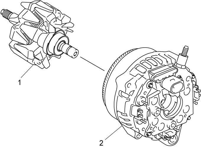
3)Install rotor (1) to stator assembly (2).
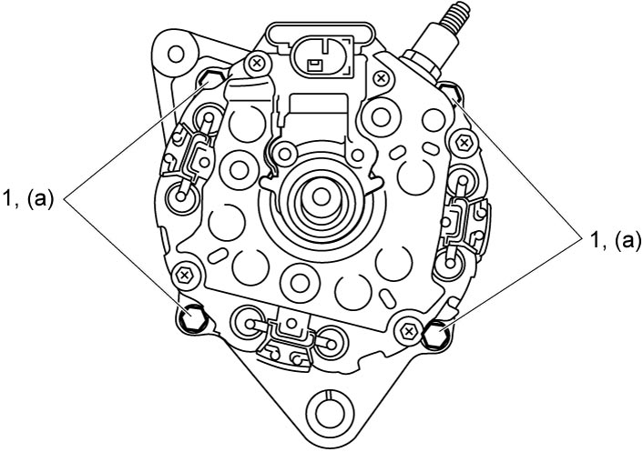
4)Install drive end frame to stator assembly, and then tighten stator assembly bolts (1) to specified torque.
NOTE:
When installing the drive end frame to the stator assembly, align matchmark provided before disassembly.
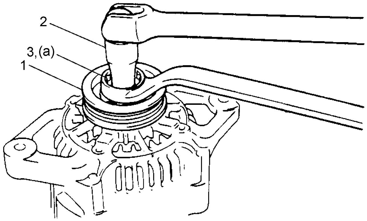
5)Install pulley (1), hold shaft using hexagonal box wrench (2), and then tighten pulley nut (3) to specified torque.
6)Install brush holder assembly (1) using the following procedure.
a)Push brushes (2) in arrow direction.
b)Hold brushes in compressed position inserting a pin (3) into stopper hole (4).
NOTE:
Recommended pin diameter: About 1.0 mm (0.04 in.)
c)Install brush holder assembly to stator assembly (5), and then tighten brush holder assembly screws (6) to specified torque.
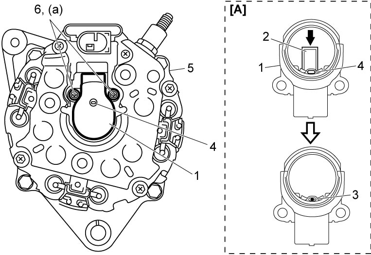
d)Remove pin from brush holder assembly.
7)Install bushing (1) to “B” terminal.