ESP® Control Module Power Supply and Ground Circuit Check
Precautions: Precautions for ESP® · Precautions for Diagnosing Trouble · Test with Speedometer Tester or Other Equipment · Precautions for Brakes · General safety (00)
Circuit Diagram
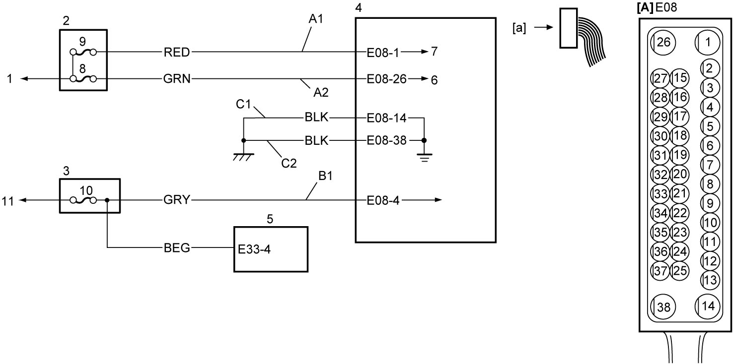
| [A]: | ESP® control module connector (View: [a]) | 1. | Lead to battery | 7. | Lead to solenoid valve power supply relay |
| A1: | Solenoid valve power supply circuit | 2. | Relay box | 8. | “ABS” fuse (25A) |
| A2: | Pump motor power supply circuit | 3. | J/B | 9. | “ABS2” fuse |
| B1: | Ignition power supply circuit | 4. | ESP® control module | 10. | “ABS” fuse (10A) |
| C1: | ESP® control module ground circuit 1 | 5. | Steering angle sensor | 11. | Ignition power supply |
| C2: | ESP® control module ground circuit 2 | 6. | Lead to pump motor relay |
Circuit Description
When the ignition is set “ON”, power is supplied to ESP® control module. Then power is supplied to pump motor and solenoid valve in other line by the switching function in ESP® control module.
Troubleshooting
| Step | Action | Yes | No |
|---|---|---|---|
| 1 |
Fuse check
Are “ABS” fuse (25A), “ABS2” fuse and “ABS” fuse (10A) in good condition?
|
Go to Step 2.
|
Replace fuse and check for short circuit to ground.
|
| 2 |
ESP® control module power supply circuit check
1)Check that ignition is “OFF”.
2)Disconnect “E08” connector.
3)Check for proper connection to “E08” connector.
4)If connections are OK, set ignition “ON”.
5)Measure voltage between “E08-4” terminal and ground.
Is it 10 – 14 V?
|
Go to Step 3.
|
Repair or replace “B1” circuit.
|
| 3 |
Pump motor and solenoid valve power supply circuit check
1)Check that ignition is “OFF”.
2)Measure voltage between each of “E08-26” and “E08-1” terminals and ground.
Are they 10 – 14 V?
|
Go to Step 4.
|
Repair or replace “A1” circuit and/or “A2” circuit.
|
| 4 |
ESP® control module ground circuit check
1)Measure resistance between each of “E08-14” and “E08-38” terminals and ground.
Is resistance less than 1 Ω?
|
ESP® control module power supply and ground circuits are in good condition.
|
Repair or replace “C1” circuit and/or “C2” circuit.
|