Yaw Rate / G Sensor Assembly On-Vehicle Inspection
Precautions: Precautions for ESP® · Precautions for Diagnosing Trouble · Test with Speedometer Tester or Other Equipment · Precautions for Brakes · General safety (00)
Longitudinal G Inspection
1)Park vehicle on level surface with parking brake applied and fix wheels with chocks.
2)Connect SUZUKI scan tool to DLC (1) with ignition “OFF”.
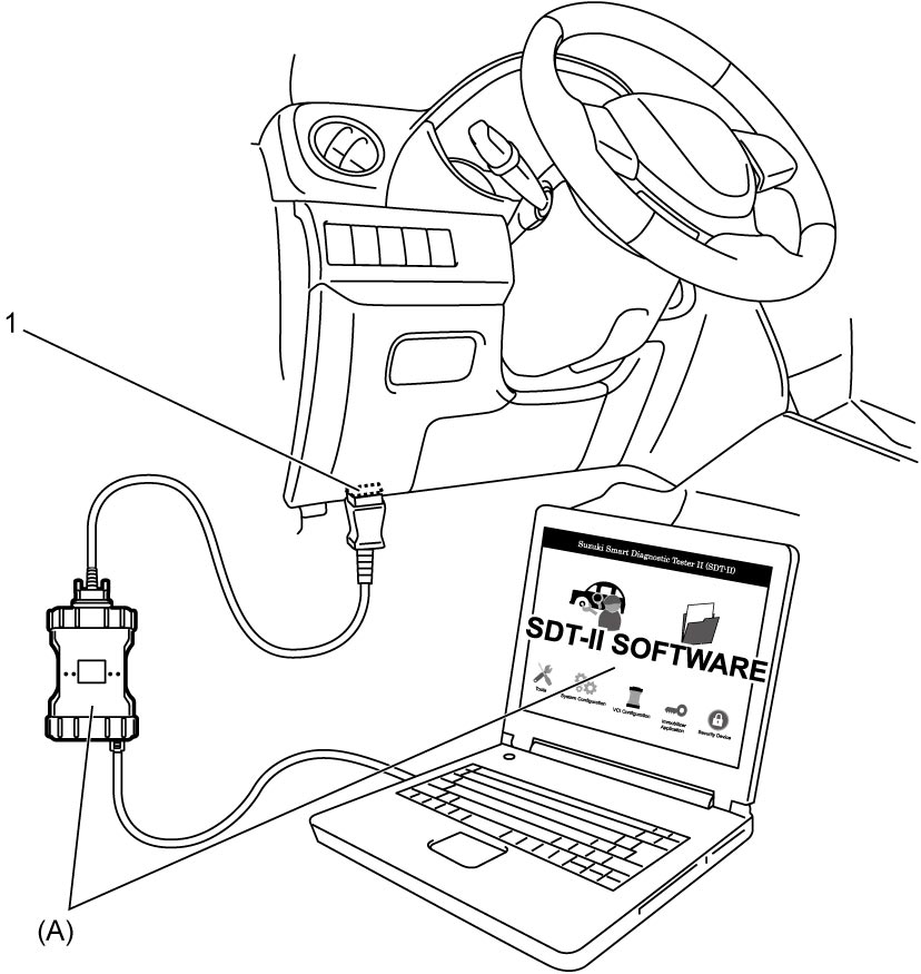

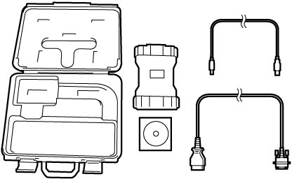
3)Calibrate yaw rate / G sensor. 
4)Set ignition “ON” and select “DATA LIST” of SUZUKI scan tool. Refer to Operator’s Manual of SUZUKI scan tool for further details.
5)Check “G Sensor” under “DATA LIST” of SUZUKI scan tool in the following vehicle conditions.
•Level condition
•Front-up condition
•Rear-up condition
Replace ESP® hydraulic unit / control module if check result is not as specified.•Front-up condition
•Rear-up condition
Longitudinal G specification
| Vehicle condition | G sensor |
|---|---|
| Level condition | 0 ± 0.1 G |
| Front-up condition | 0.1 ± 0.1 G |
| Rear-up condition | –0.1 ± 0.1 G |
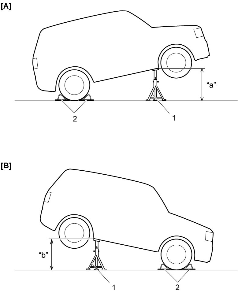
| [A]: | Front-up condition | “b”: | Approx. 380 mm (14.9 in.) |
| [B]: | Rear-up condition | 1. | Safety stand |
| “a”: | Approx. 370 mm (14.5 in.) | 2. | Chock |
Lateral G Inspection
1)Park vehicle on level surface with parking brake applied and fix wheels with chocks.
2)Connect SUZUKI scan tool to DLC (1) with ignition “OFF”.
3)Calibrate yaw rate / G sensor.
4)Set ignition “ON” and select “DATA LIST” of SUZUKI scan tool. Refer to Operator’s Manual of SUZUKI scan tool for further details.
5)Check “G Sensor (Lateral)” under “DATA LIST” of SUZUKI scan tool in the following vehicle conditions.
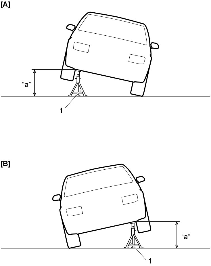
•Level condition
•Right-up condition
•Left-up condition
Replace ESP® hydraulic unit / control module if check result is not as specified.
•Right-up condition
•Left-up condition
Lateral G specification
| Vehicle condition | G sensor (lateral) |
|---|---|
| Level condition | 0 ± 0.1 G |
| Right-up condition | 0.1 ± 0.1 G |
| Left-up condition | –0.1 ± 0.1 G |
| [A]: | Right-up condition | “a”: | Approx. 350 mm (13.7 in.) |
| [B]: | Left-up condition | 1. | Safety stand |
Yaw Rate Inspection
1)Connect SUZUKI scan tool to DLC (1) with ignition “OFF”.
2)Calibrate yaw rate / G sensor.
3)Set ignition “ON” and select “DATA LIST” of SUZUKI scan tool. Refer to Operator’s Manual of SUZUKI scan tool for further details.
4)Check “Yaw Rate Sensor” under “DATA LIST” of SUZUKI scan tool in the following vehicle conditions.
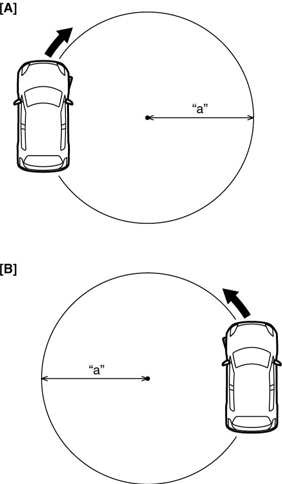
•Parking condition
•Drive vehicle in right turning condition with steering wheel fully turned.
•Drive vehicle in left turning condition with steering wheel fully turned.
Replace ESP® hydraulic unit / control module if check result is not as specified.
•Drive vehicle in right turning condition with steering wheel fully turned.
•Drive vehicle in left turning condition with steering wheel fully turned.
Yaw rate specification
| Vehicle condition | Yaw rate |
|---|---|
| Parking | 0 ± 4 deg/s |
| Right turning | 45.0 ± 5 deg/s |
| Left turning | –45.0 ± 5 deg/s |
NOTE:
•Drive vehicle on a level surface at 10 km/h (6 mile/h).
•Turning radius is 5.2 m (17.1 ft.).
•Turning radius is 5.2 m (17.1 ft.).
| [A]: | Right turning | “a”: | Approx. 5.2 m (17.1 ft.) |
| [B]: | Left turning |