TCM Power and Ground Circuit Check
Precautions: Precautions for Diagnosing Trouble · Precautions for Disassembly and Reassembly · Precautions for Transmission / Transaxle · General safety (00)
Circuit Diagram
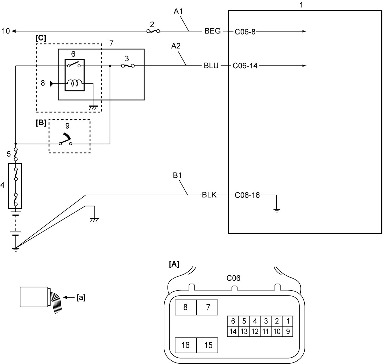
| [A]: | TCM connector (View: [a]) | 1. | TCM | 7. | J/B |
| [B]: | Ignition switch model | 2. | “T/M5” fuse (ENG A-STOP model) or “T/M1” fuse (Non-ENG A-STOP model) | 8. | To keyless start control module |
| [C]: | Keyless push start model | 3. | “IG1 SIG” fuse | 9. | Ignition switch |
| A1: | Main power supply circuit | 4. | Main fuse box | 10. | To DC/DC converter (ENG A-STOP model) or battery (Non-ENG A-STOP model) |
| A2: | Ignition power supply circuit | 5. | “IGN” fuse | ||
| B1: | TCM ground circuit | 6. | IG1 relay |
Troubleshooting
| Step | Action | Yes | No |
|---|---|---|---|
| 1 |
Main power supply circuit check
1)Set ignition “OFF” and disconnect connector from TCM.
2)Check for proper terminal connection to TCM connector.
3)If connection is OK, check that voltage between “A1” circuit and ground is battery voltage.
Is check result OK?
|
Go to Step 2.
|
Repair or replace defective wire harness.
|
| 2 |
Ignition power supply circuit check
1)Set ignition “ON”.
2)Check that voltage between “A2” and “B1” circuit is battery voltage.
Is check result OK?
|
TCM power and ground circuit are in good condition.
|
Go to Step 3.
|
| 3 |
TCM ground circuit check
1)Set ignition “OFF”.
2)Check that resistance between “B1” circuit and ground is less than 1 Ω.
Is check result OK?
|
Repair or replace “A2” circuit.
|
Repair or replace “B1” circuit.
|