Input Shaft Disassembly and Reassembly
Precautions: General safety (00)
 CAUTION:
Using an inappropriate hydraulic press or bearing puller could cause personal injury.
Use the hydraulic press and bearing puller which are capable of safely bearing a load of at least 5 tons (11,000 lbs).
NOTICE:
Supporting the gear on the concave side of the puller can cause damage to the gear.
Support the gear on the flat side of the puller.
Disassembly
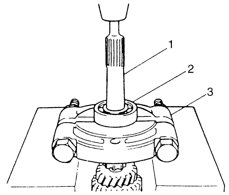
1)Remove input shaft right bearing (2) from input shaft (1) using bearing puller (3) and hydraulic press.

2)Remove 5th gear spacer (2), left bearing (3) and 4th gear (4) all together using puller (5) and hydraulic press.
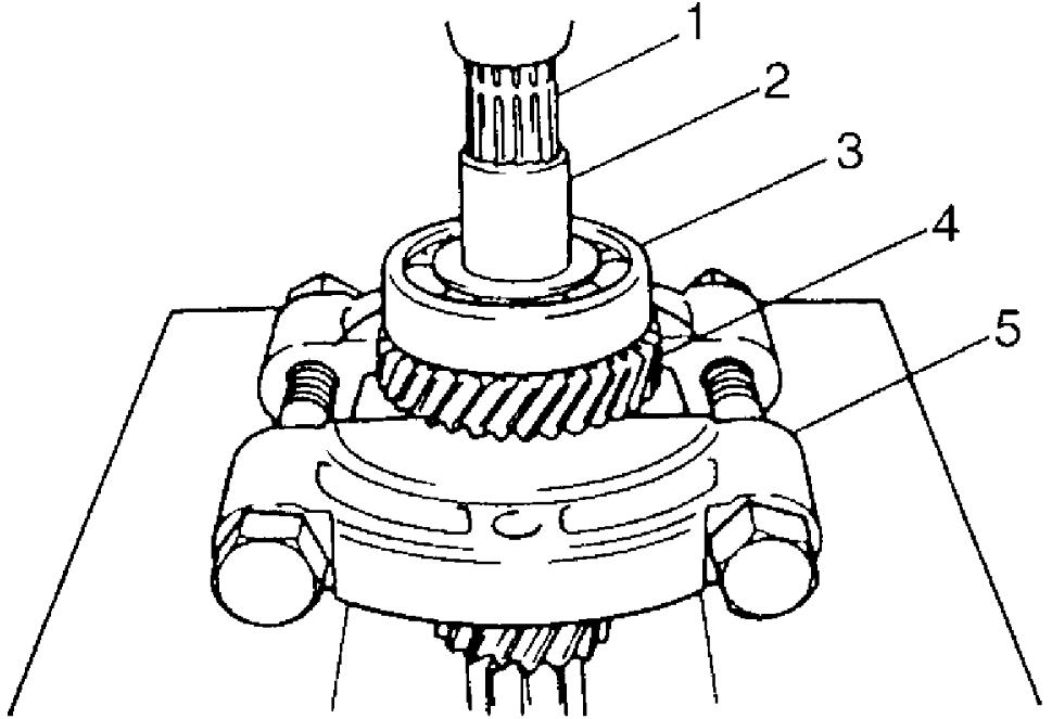
| 1. | Input shaft |
3)Remove 4th gear needle bearing and high speed synchronizer ring.
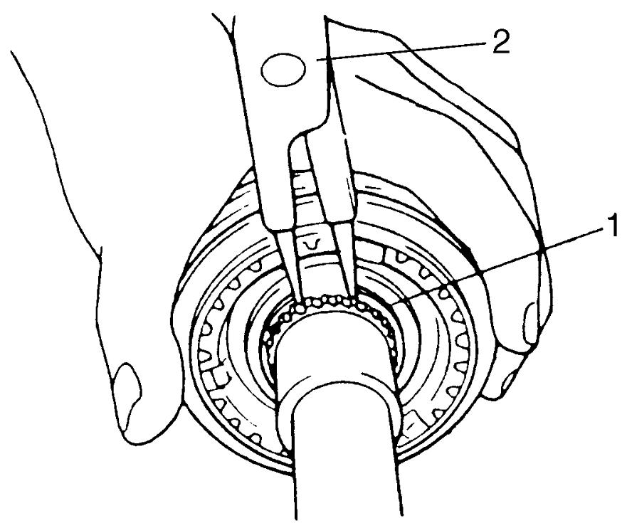
4)Using snap ring pliers (2), remove circlip (1).
5)Remove high speed synchronizer sleeve & hub assembly (2) together with 3rd gear (3) using puller (4) and hydraulic press.
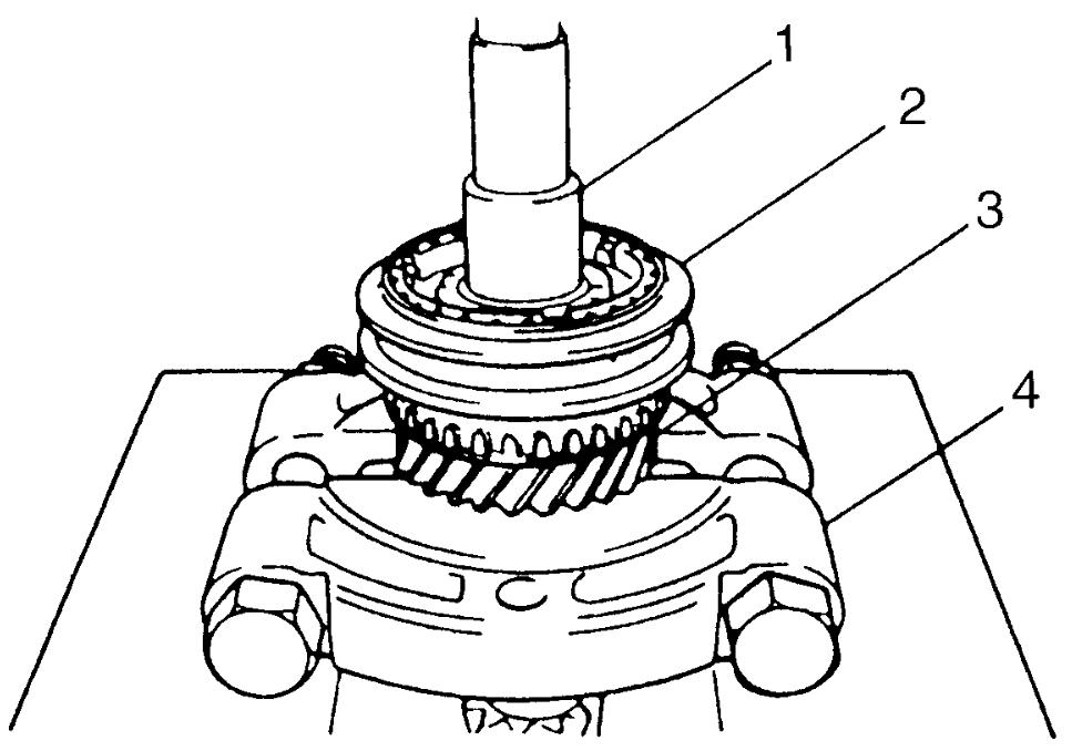
| 1. | Input shaft |
6)Remove 3rd gear needle bearing from input shaft.
7)Disassemble synchronizer sleeve & hub assembly.
Reassembly
1)Clean all components thoroughly, check them for any abnormal condition and replace defective parts with new ones if necessary.
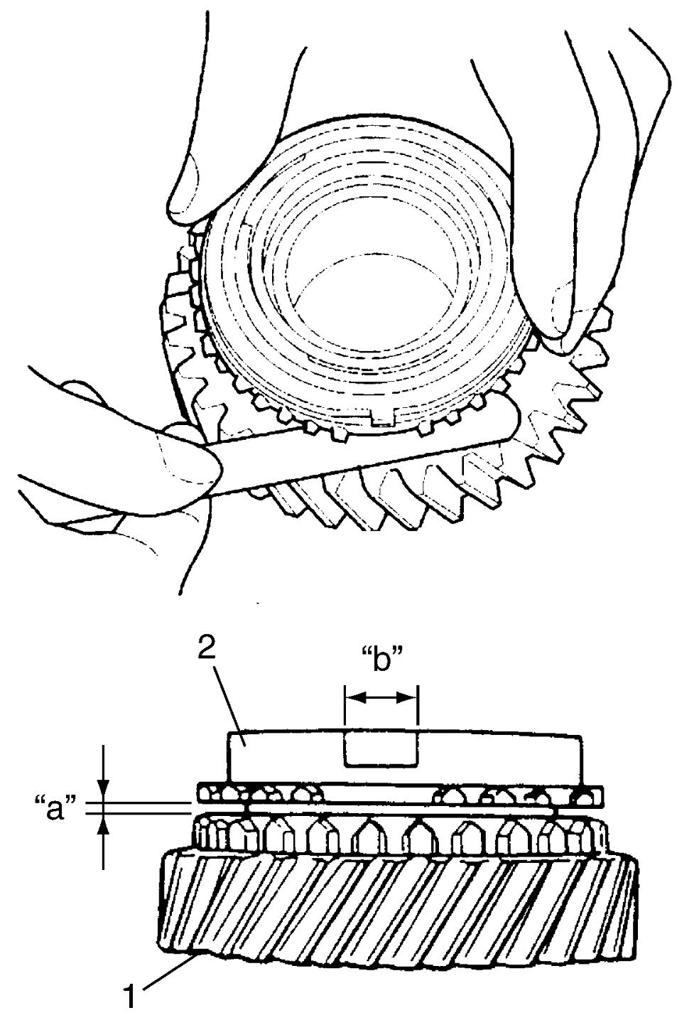
2)Check clearance “a” between synchronizer ring (2) and gear (1), key slot width “b” in synchronizer ring and replace defective part with new one, if necessary. Also, check gear teeth for damage.
Clearance “a” between synchronizer ring and gear
Standard: 1.0 – 1.4 mm (0.040 – 0.055 in.)
Limit: 0.5 mm (0.020 in.)
Key slot width “b”
Standard: 10.0 – 10.2 mm (0.394 – 0.401 in.)
Limit: 10.45 mm (0.4114 in.)
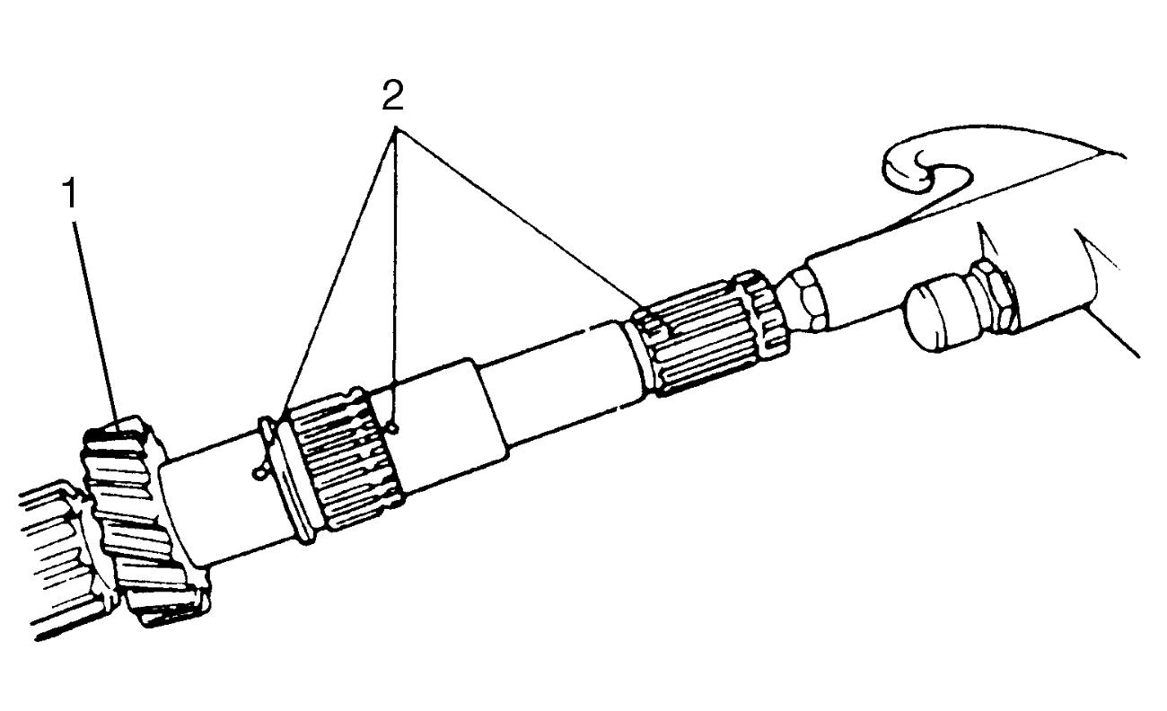
3)To ensure lubrication of input shaft (1), blow air into oil holes (2) as shown in figure and check that they are free from any obstruction.
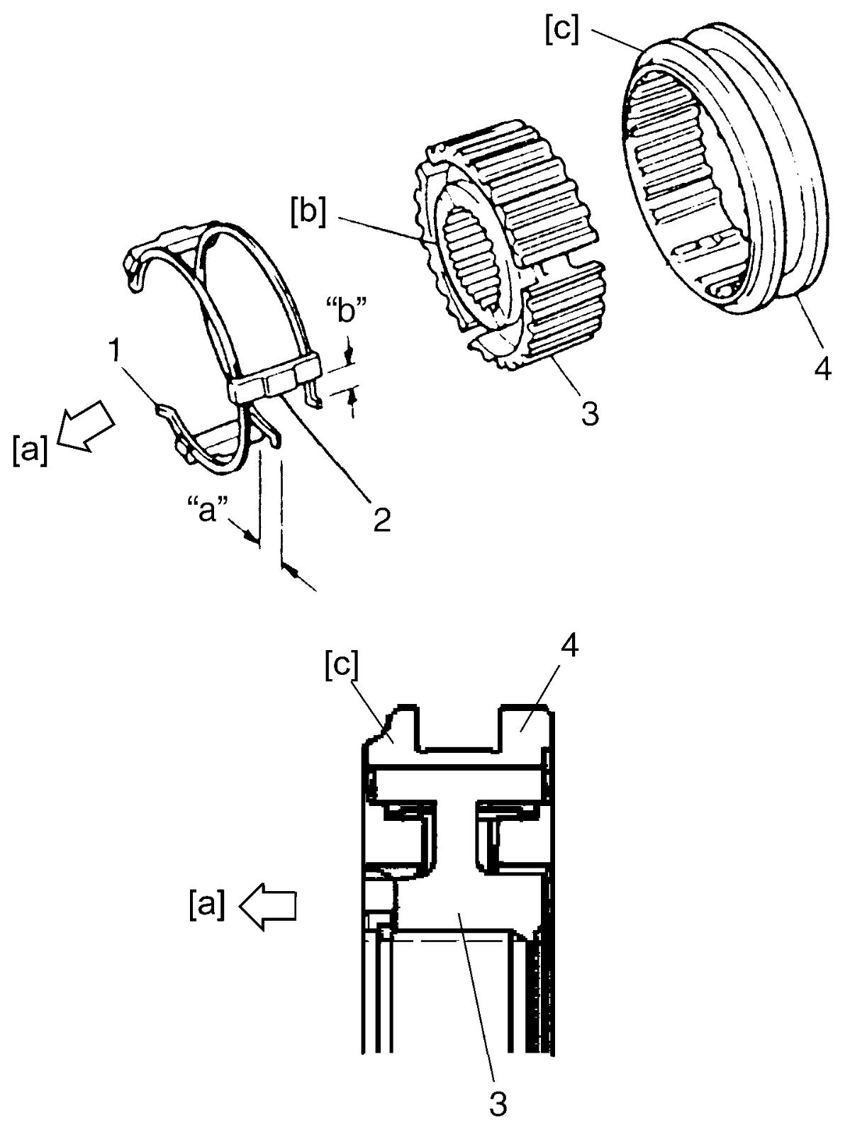
4)Fit high speed synchronizer sleeve (4) to hub (3), insert 3 keys (2) in it and then set springs at specified position (1) as shown in figure.
NOTE:
•Assemble sleeve and hub in correct direction. (No direction is specified to each key.)
•Sizes of high speed synchronizer sleeve, hub, keys and springs are between sizes of low speed ones and 5th speed ones.
•Sizes of high speed synchronizer sleeve, hub, keys and springs are between sizes of low speed ones and 5th speed ones.
Synchronizer key installation position
“a” = “b”
| [a]: | 4th gear side | [c]: | Projecting end |
| [b]: | Short flange side |
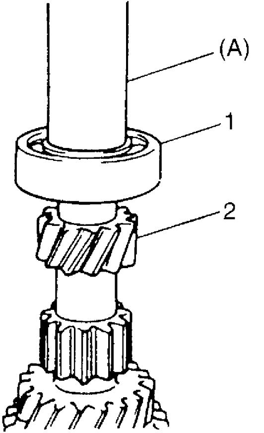
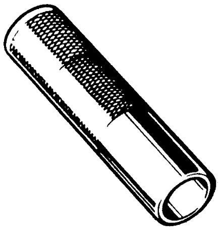
5)Install right bearing (1) to input shaft (2) using special tool and hydraulic press.
6)Install 3rd gear needle bearing (4), apply oil to it, and then install 3rd gear (1) and synchronizer ring (2).
7)Install high speed sleeve & hub assembly (3) using special tool and hydraulic press.
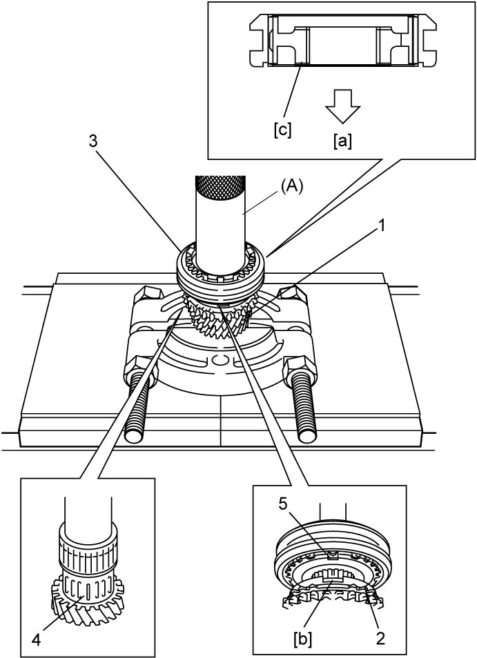
NOTE:
•Check that synchronizer ring key slots are aligned with keys (5) in sleeve & hub assembly.
•Check free rotation of 3rd gear after press-fitting sleeve & hub assembly.
•Check free rotation of 3rd gear after press-fitting sleeve & hub assembly.
| [a]: | 3rd gear side | [c]: | Long flange |
| [b]: | Key way |
8)Install new circlip (1) to groove securely.
9)Install needle bearing (2), apply oil to it and then install synchronizer ring (3) and 4th gear (4).
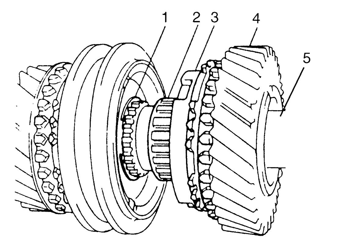
| 5. | Input shaft |
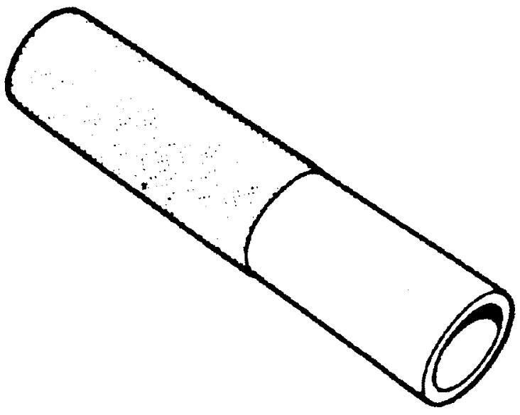
10)Press-fit left bearing (2) using special tool and hydraulic press.
11)Using the same special tool as in Step 10), install 5th gear spacer (1).
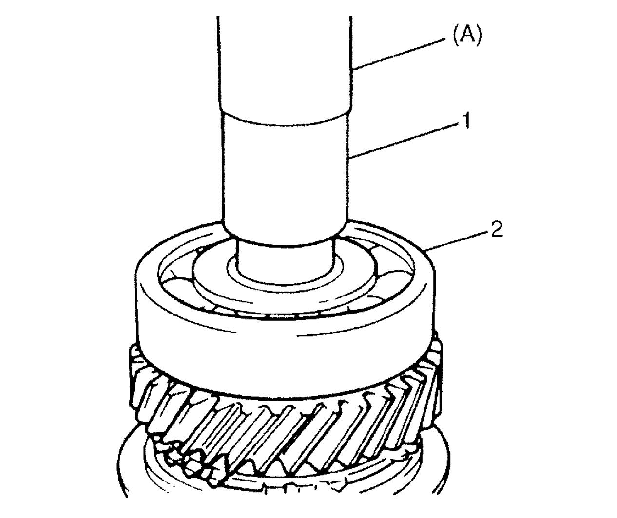
NOTICE:
Press-fitting left bearing (2) and 5th gear spacer (1) together can cause distortion of spacer.
Do not press-fit left bearing using spacer.