DTC P0571-24
Precautions: Precautions for Diagnosing Trouble · Precautions for Disassembly and Reassembly · Precautions for Transmission / Transaxle · General safety (00)
DTC Detecting Condition and Trouble Area
| DTC detecting condition | Trouble area |
|---|---|
|
P0571-24: Brake Switch “A” – Signal Stuck High Brake switch signal is stuck ON for specified time although the odd clutch speed or even clutch speed is higher than specified value. (1 D/C detection logic but transmission warning light does not light up) |
•Brake light switch and/or its circuit
•TCM power supply circuit and/or ground circuit •TCM |
Circuit Diagram
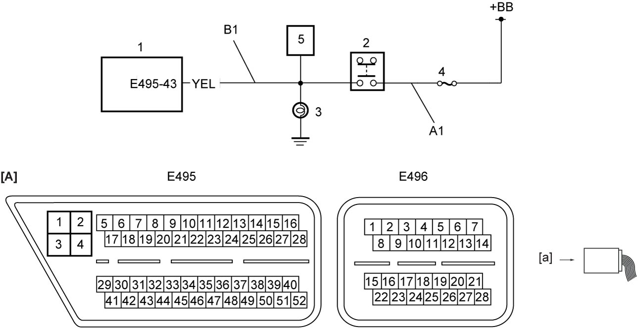
| [A]: | TCM connector (View: [a]) | 1. | TCM | 4. | “STOP” fuse |
| A1: | Brake light switch power supply circuit | 2. | Brake light switch | 5. | Keyless start control module |
| B1: | Brake light switch signal circuit | 3. | Brake light |
DTC Confirmation Procedure
 WARNING:
If you do not select a suitable route and take proper precautions when performing a road test, an accident can occur.
•Select a level road with no traffic to minimize the risk of accident.
•Perform the test extremely carefully.
•Perform the road test with 2 persons, a driver and a tester.
•Perform the test extremely carefully.
•Perform the road test with 2 persons, a driver and a tester.
NOTE:
•Check that the following condition is satisfied in this procedure.
—11 V < Battery voltage < 15 V
•Check that the following DTCs are not detected in this “DTC Confirmation Procedure.”
—Brake light switch (P0703-63, P0703-68 and P0719-13)
—CAN communication (U0141-87)
—CAN communication (U0141-87)
1)Start engine and drive vehicle.
DTC Troubleshooting
| Step | Action | Yes | No |
|---|---|---|---|
| 1 |
Was “Twin Clutch System Check” performed?
|
Go to Step 2.
|
Go to Twin Clutch System Check.
|
| 2 |
Brake light switch power supply circuit check
1)With ignition “OFF”, disconnect brake light switch connector.
2)Check for proper terminal connection to brake light switch connector.
3)If connection is OK, check that voltage between “A1” circuit and ground is battery voltage.
Is check result OK?
|
Go to Step 3.
|
Repair or replace defective wire harness.
|
| 3 |
Brake light switch signal circuit check
1)Disconnect “E495” connectors from TCM.
2)Check for proper terminal connection to “E495” connector.
3)If connection is OK, check the following points.
•Resistance of “B1” circuit: less than 1 Ω
•Resistance between “B1” circuit and ground: infinity •Resistance between “B1” circuit terminal and other terminal at brake light switch connector: infinity •Voltage of “B1” circuit: approx. 0 V (When ignition is “ON”) Is check result OK?
|
Go to Step 4.
|
Repair or replace defective wire harness.
|
| 4 |
Brake light switch check
1)Check brake light switch.

Is check result OK?
|
Replace TCM and recheck DTC.
|
Replace brake light switch.
|