P/S Control Module Power Supply and Ground Circuit Check
Precautions: Precautions for Diagnosing Trouble · Precautions for Steering · General safety (00)
Circuit Diagram
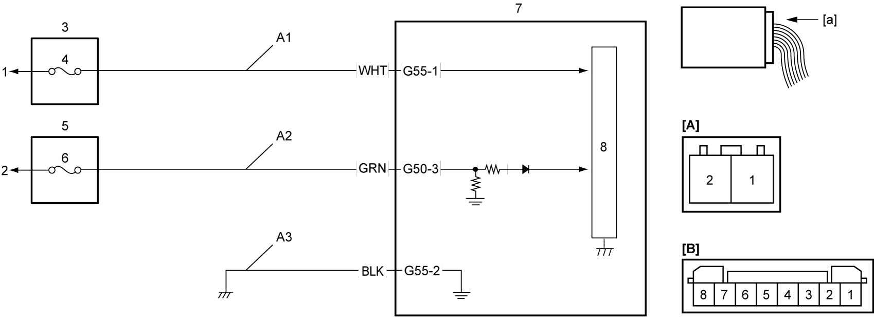
| [A]: | P/S control module connector “G55” (View: [a]) | 1. | To continuous power supply | 6. | “IG1 SIG” fuse |
| [B]: | P/S control module connector “G50” (View: [a]) | 2. | To ignition power supply | 7. | P/S control module / motor assembly |
| A1. | P/S control module power supply circuit | 3. | Main fuse box | 8. | CPU |
| A2. | IG1 power supply circuit | 4. | “P/S” fuse | ||
| A3. | P/S control module ground circuit | 5. | J/B |
Troubleshooting
| Step | Action | Yes | No |
|---|---|---|---|
| 1 |
Circuit fuse check
1)Check that ignition is “OFF”.
2)Disconnect “G55” and “G50” connectors.
3)Check for proper connection to “G50-3” and “G55-1” terminals.
4)If connections are OK, check “P/S” fuse and “IG1 SIG” fuse for blowing.
Is check result OK?
|
Go to Step 2.
|
Replace fuse(s) and check for short to ground in circuits connected to fuse(s).
|
| 2 |
P/S control module power supply circuit check
1)Check voltage between “G55-1” terminal and ground.
Is voltage 10 – 14 V?
|
Go to Step 3.
|
“A1” circuit is open.
|
| 3 |
IG1 power supply circuit check
1)Set ignition “ON”.
2)Check voltage between “G50-3” terminal and ground.
Is voltage 10 – 14 V?
|
Go to Step 4.
|
“A2” circuit is open.
|
| 4 |
P/S control module ground circuit check
1)Set ignition “OFF”.
2)Check for proper connection to “G55-2” terminal.
3)Check resistance between “G55-2” terminal and ground.
Is resistance 1 Ω or less?
|
End.
|
“A3” circuit is open or too high in resistance.
|