Manual A/C and Additional Heater (If Equipped) System Circuit Diagram
Precautions: General safety (00)
Petrol Model
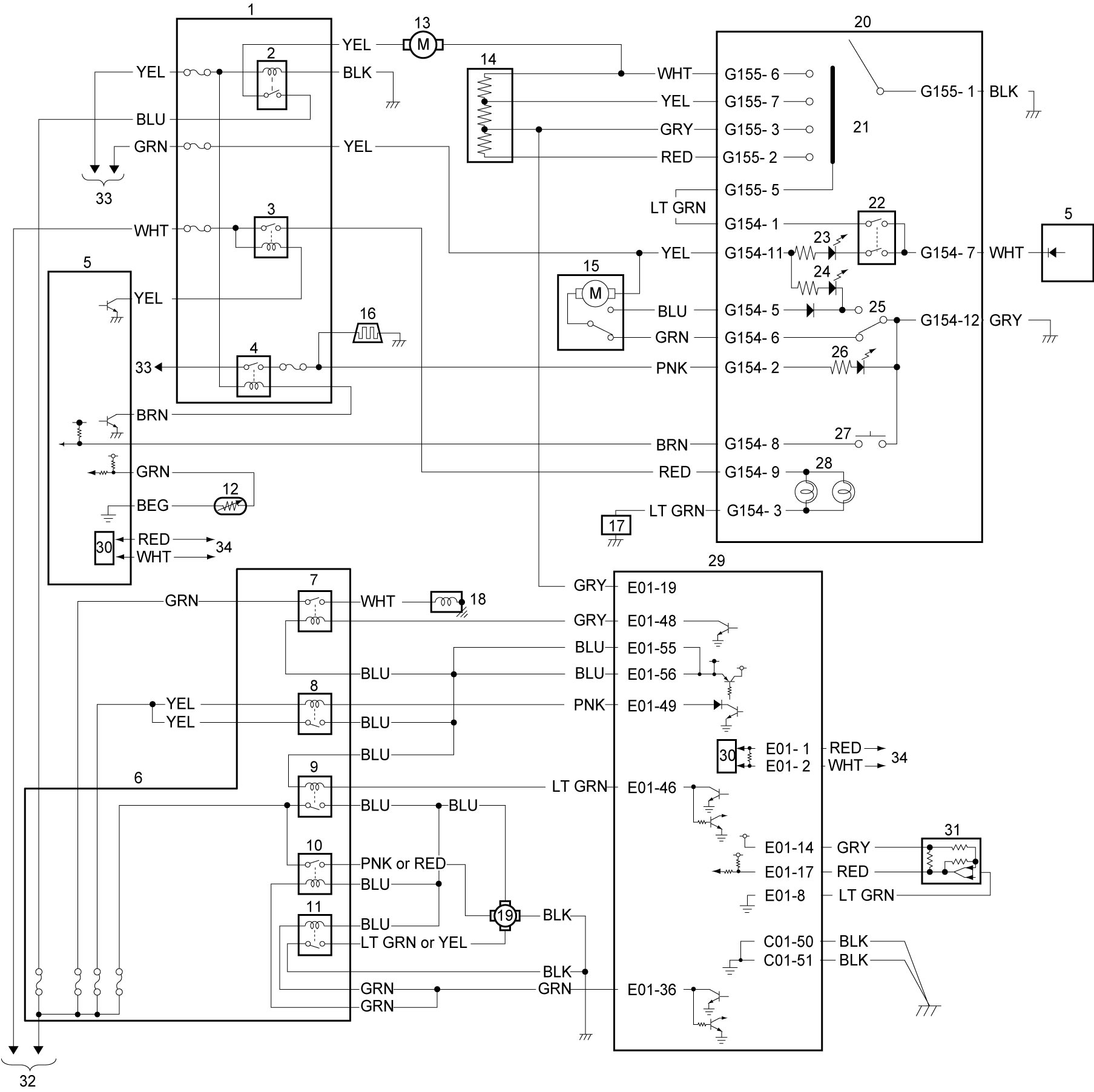
| 1. | J/B | 13. | Blower motor | 25. | Air intake switch |
| 2. | Blower motor relay | 14. | Blower motor resistor | 26. | Rear defogger indicator light |
| 3. | Tail light relay | 15. | Air intake control actuator | 27. | Rear defogger switch |
| 4. | Rear defogger and mirror heater relay | 16. | Rear defogger | 28. | Illumination light |
| 5. | BCM | 17. | Combination meter | 29. | ECM |
| 6. | Relay box | 18. | Compressor | 30. | CAN driver |
| 7. | A/C compressor relay | 19. | Radiator cooling fan motor | 31. | A/C refrigerant pressure sensor |
| 8. | Main relay | 20. | HVAC control unit | 32. | To continuous power supply |
| 9. | Radiator cooling fan relay No.1 | 21. | Blower speed selector | 33. | To ignition power supply |
| 10. | Radiator cooling fan relay No.2 | 22. | A/C switch | 34. | To other control module and DLC connected by CAN |
| 11. | Radiator cooling fan relay No.3 | 23. | “A/C” indicator light | ||
| 12. | Evaporator temperature sensor | 24. | “REC” indicator light |
Diesel Model
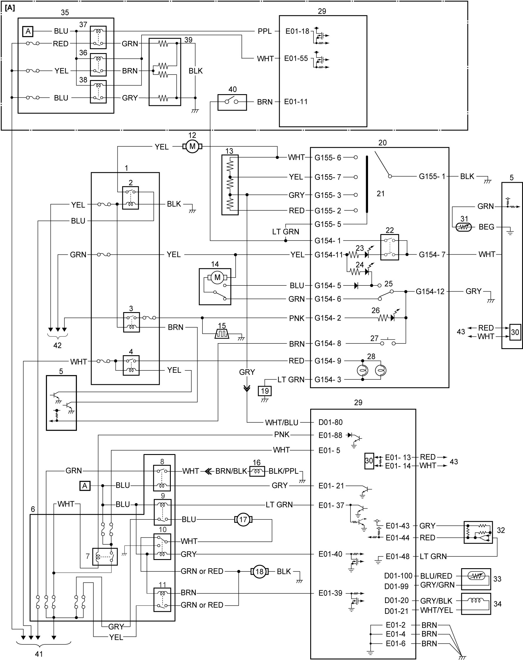
| [A]: | Additional heater system circuit (if equipped) | 15. | Rear defogger | 30. | CAN driver |
| 1. | J/B | 16. | Compressor | 31. | Evaporator temperature sensor |
| 2. | Blower motor relay | 17. | Radiator cooling main fan motor | 32. | A/C refrigerant pressure sensor |
| 3. | Rear defogger and mirror heater relay | 18. | Radiator cooling sub fan motor | 33. | ECT sensor |
| 4. | Tail light relay | 19. | Combination meter | 34. | CKP sensor |
| 5. | BCM | 20. | Radiator cooling sub fan motor | 35. | Sub fuse box |
| 6. | Relay box | 21. | Blower speed selector | 36. | Additional heater relay No.1 |
| 7. | Main relay | 22. | A/C switch | 37. | Additional heater relay No.2 |
| 8. | A/C compressor relay | 23. | “A/C” indicator light | 38. | Additional heater relay No.3 |
| 9. | Radiator cooling fan relay No.1 | 24. | “REC” indicator light | 39. | Additional heater assembly |
| 10. | Radiator cooling fan relay No.2 | 25. | Air intake switch | 40. | Max hot switch |
| 11. | Radiator cooling fan relay No.3 | 26. | Rear defogger indicator light | 41. | To continuous power supply |
| 12. | Blower motor | 27. | Rear defogger switch | 42. | To ignition power supply |
| 13. | Blower motor resistor | 28. | Illumination light | 43. | To other control module and DLC connected by CAN |
| 14. | Air intake control actuator | 29. | ECM |