Auto A/C Control System Component Location
Precautions: Precautions for Diagnosing Trouble · General safety (00)
NOTE:
This figure shows the component locations for LHD as an example.
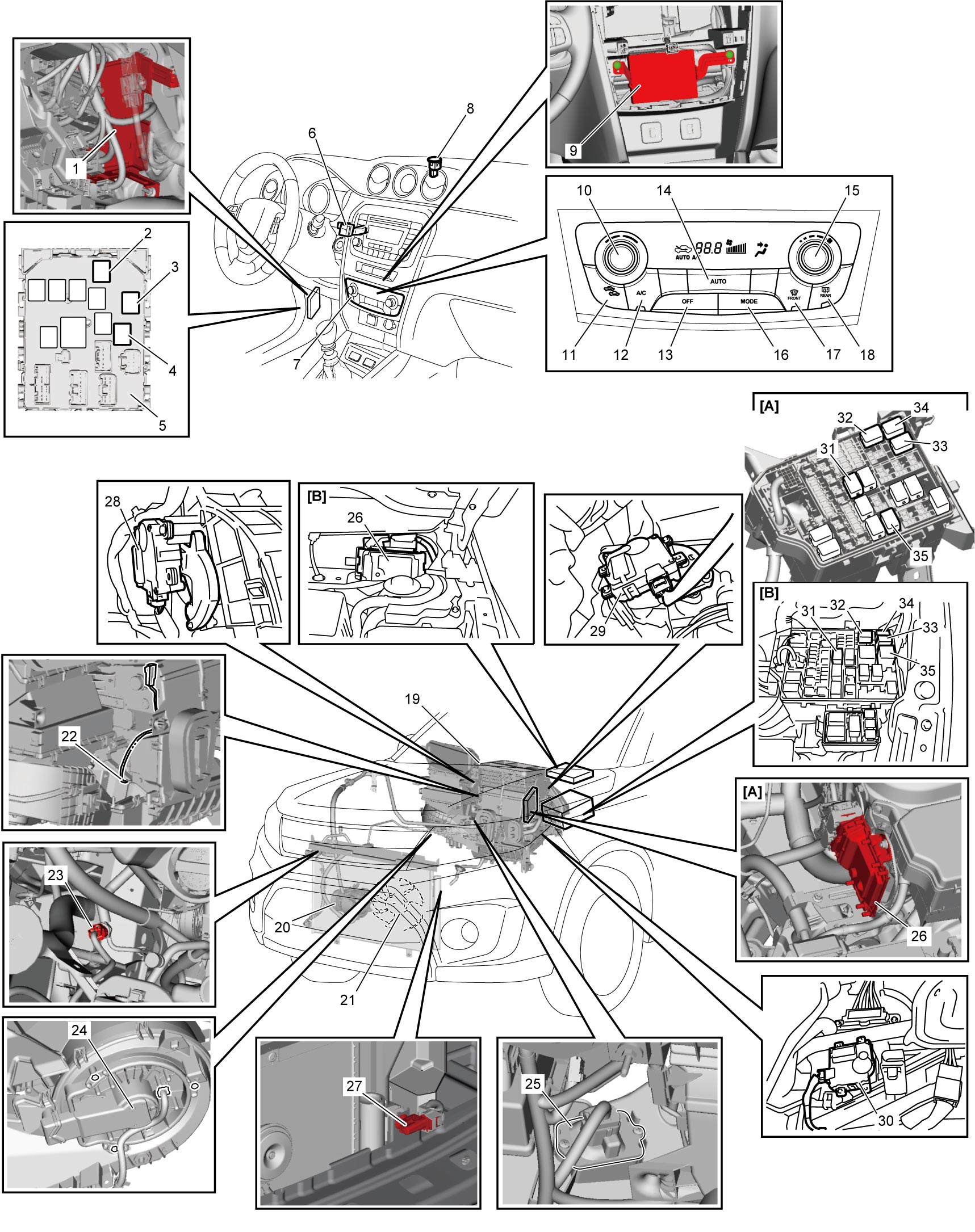
| [A]: | Petrol model | 12. | A/C switch | 25. | Blower motor controller |
| [B]: | Diesel model | 13. | “OFF” switch | 26. | ECM |
| 1. | BCM | 14. | “AUTO” switch | 27. | Outside air temperature sensor |
| 2. | Tail light relay | 15. | Blower speed selector | 28. | Air intake control actuator |
| 3. | Blower motor relay | 16. | “MODE” (air flow) switch | 29. | Air flow control actuator |
| 4. | Rear defogger and mirror heater relay | 17. | Defroster switch | 30. | Temperature control actuator |
| 5. | J/B | 18. | Rear defogger switch | 31. | A/C compressor relay |
| 6. | Inside air temperature sensor | 19. | HVAC unit | 32. | Radiator cooling fan relay No.1 |
| 7. | Auto A/C panel | 20. | Compressor | 33. | Radiator cooling fan relay No.2 |
| 8. | Sunload sensor | 21. | Radiator cooling fan | 34. | Radiator cooling fan relay No.3 |
| 9. | HVAC control module | 22. | Evaporator temperature sensor | 35. | Main relay |
| 10. | Temperature selector | 23. | A/C refrigerant pressure sensor | ||
| 11. | Air intake switch | 24. | Blower motor |