A/C System Performance Inspection
Precautions: Precautions for Diagnosing Trouble · General safety (00)
M16A Model and D16AA Model
K14C Model
1)Check that vehicle and environmental conditions are as follows.
•Vehicle is put indoors.
•Ambient temperature is within 25 – 35 °C (77 – 95 °F).
•Relative humidity is within 30 – 70%.
•There is no wind indoors.
•HVAC unit is normal.
•Blower motor is normal.
•There is no air leakage from air ducts.
•Condenser fins are clean.
•HVAC air filter is not clogged with dirt and dust.
•Battery voltage is about 12 V or more (battery in good condition).
•Radiator cooling fan operates normally.
•Ambient temperature is within 25 – 35 °C (77 – 95 °F).
•Relative humidity is within 30 – 70%.
•There is no wind indoors.
•HVAC unit is normal.
•Blower motor is normal.
•There is no air leakage from air ducts.
•Condenser fins are clean.
•HVAC air filter is not clogged with dirt and dust.
•Battery voltage is about 12 V or more (battery in good condition).
•Radiator cooling fan operates normally.
2)Check that high pressure valve (1) and low pressure valve (2) of manifold gauge are firmly closed.
3)Connect high pressure charging hose (3) to high pressure service valve (4) and low pressure charging hose (5) to low pressure service valve (6).
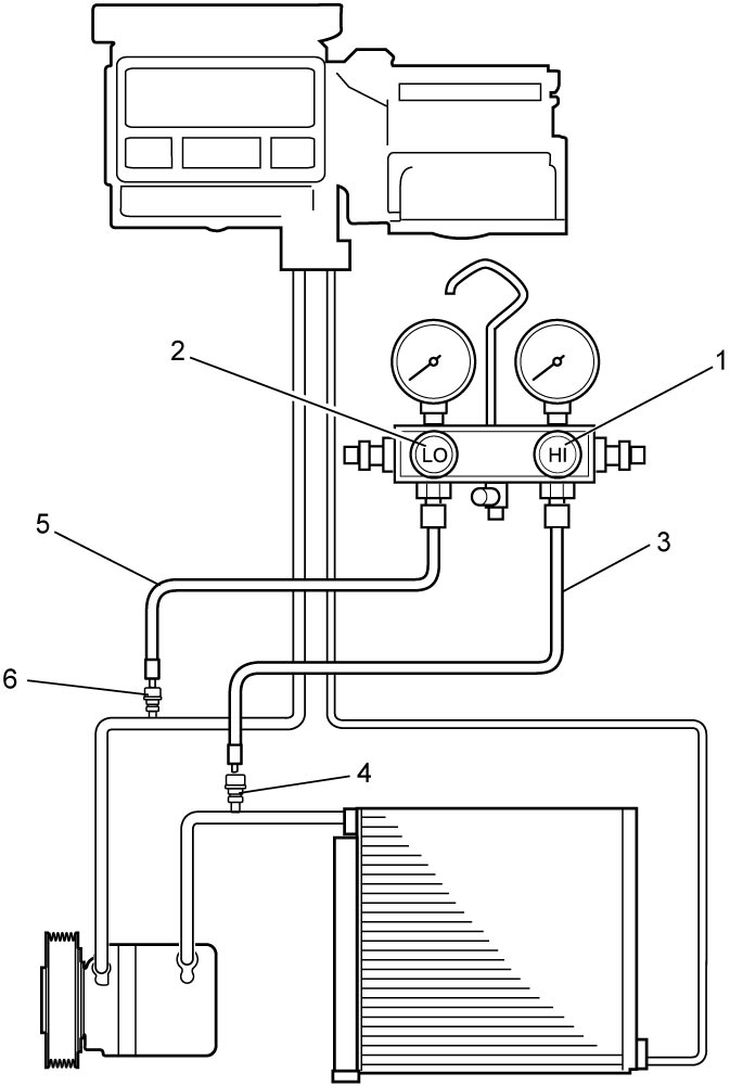

NOTE:
•For locations of high pressure service valve and low pressure service valve, refer to A/C System Major Components:Automatic Type.
•The HVAC system of this vehicle is filled with either of two refrigerant types, HFC-134a or HFO-1234yf. And, service valves for each refrigerant type have different dimensions. Use manifold gauge set compatible with respective refrigerant.
•The HVAC system of this vehicle is filled with either of two refrigerant types, HFC-134a or HFO-1234yf. And, service valves for each refrigerant type have different dimensions. Use manifold gauge set compatible with respective refrigerant.
4)Warm up engine to normal operating temperature and keep it at specified idle speed.
5)Turn A/C switch ON, and then set blower speed selector to maximum speed position, temperature selector to maximum cold position, “MODE” (air flow) switch to face position, air intake switch to recirculation mode and side ventilation louvers to open position. (Check that compressor and radiator cooling fan are working.)
6)Wait for ten minutes to stabilize A/C operation.
7)Open all door windows, front doors and hood.
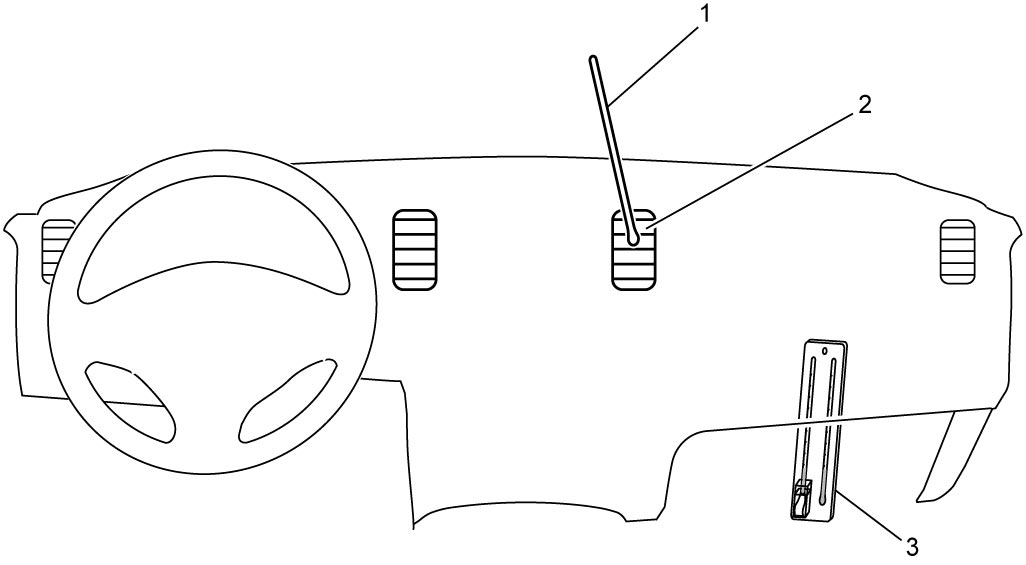
8)Put about 20 mm (0.8 in.) of dry-bulb thermometer (1) in front of center ventilation louver (2). Put wet-and-dry-bulb thermometer (3) near air inlet of HVAC unit.
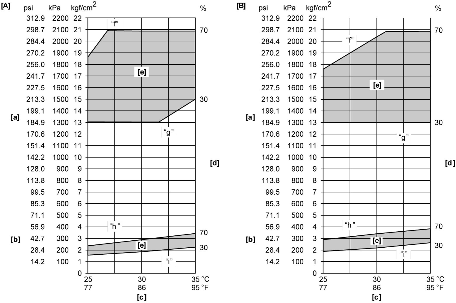
9)Check for each pressure of low side and high side if it is within shaded range in the following graph. If each gauge reading is out of specified pressure, correct defective part referring to the following table.
When diagnosing troubles of abnormal pressure on the low side and high side more specifically, refer to Trouble Diagnosis for Abnormal Pressure:Automatic Type.
When diagnosing troubles of abnormal pressure on the low side and high side more specifically, refer to Trouble Diagnosis for Abnormal Pressure:Automatic Type.
NOTE:
Pressure registered on gauge varies with ambient temperature. Therefore, use the graphs when determining if pressures are normal or not.
Low side and high side pressure example. Gauges should read as follows when ambient temperature is 30 °C (86 °F)
| HFC-134a | HFO-1234yf | |
|---|---|---|
| Pressure on high pressure gauge (HI) | 1300 – 2090 kPa (13.3 – 21.3 kgf/cm2) (188 – 303 psi) |
1300 – 2040 kPa (13.3 – 20.8 kgf/cm2) (188 – 295 psi) |
| Pressure on low pressure gauge (LO) | 190 – 290 kPa (2.0 – 2.9 kgf/cm2) (27.5 – 42.0 psi) |
220 – 340 kPa (2.3 – 3.4 kgf/cm2) (31.9 – 49.3 psi) |
| [A]: | HFC-134a model | [b]: | Pressure on low pressure gauge | [e]: | Acceptable range |
| [B]: | HFO-1234yf model | [c]: | Ambient temperature | ||
| [a]: | Pressure on high pressure gauge | [d]: | Humidity |
High pressure gauge
| Condition | Possible cause | Correction |
|---|---|---|
| Pressure is higher than acceptable range (“f” area) |
Refrigerant overcharged | Recharge. |
| Expansion valve frozen or clogged | Check expansion valve. | |
| Clogged refrigerant passage of high pressure side | Clean or replace. | |
| Radiator cooling fan malfunction (insufficient cooling of condenser) | Check radiator cooling fan. | |
| Dirty or bent condenser fins (insufficient cooling of condenser) | Clean or repair. | |
| Compressor malfunction (insufficient oil etc.) | Check compressor. | |
| Engine overheat | Check engine cooling system. 
|
|
| Pressure is lower than acceptable range (“g” area) |
Insufficient refrigerant (insufficient charge or leakage) | Check for leakage, repair if necessary and recharge. |
| Expansion valve malfunction (valve opens too wide) | Check expansion valve. | |
| Compressor malfunction (insufficient compression) | Check compressor. |
Low pressure gauge
| Condition | Possible cause | Correction |
|---|---|---|
| Pressure is higher than acceptable range (“h” area) |
Expansion valve malfunction (valve opens too wide) | Check expansion valve. |
| Compressor malfunction (insufficient compression) | Check compressor. | |
| Pressure is lower than acceptable range (“i” area) |
Insufficient refrigerant (insufficient charge or leakage) | Check for leakage, repair if necessary and recharge. |
| Expansion valve malfunction (valve opens too narrow) | Check expansion valve. | |
| Clogged refrigerant passage (crashed pipe) | Repair or replace. |
10)Check correlation between inlet port temperature and outlet port temperature using the graph. For example, if temperature near air inlet of HVAC unit is 30 °C (86 °F) and the one at air outlet of center ventilation louver is 14 °C (57.2 °F), their crossing point is within acceptable range as shown in the graph. In this case, cooling performance is satisfactory and proper.
11)If crossing point is out of acceptable range, diagnose trouble referring to the following table.
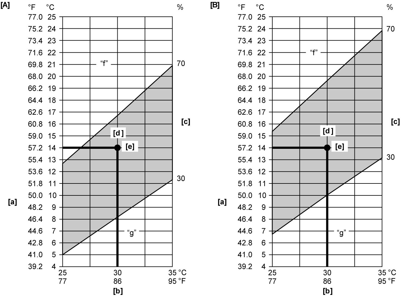
| [A]: | HFC-134a model | [b]: | Temperature near air inlet of HVAC unit | [e]: | Crossing point |
| [B]: | HFO-1234yf model | [c]: | Humidity | ||
| [a]: | Temperature at outlet of center ventilation louver | [d]: | Acceptable range |
Thermometer at center ventilation louver
| Condition | Possible cause | Correction |
|---|---|---|
| Crossing point is higher than acceptable range (“f” area) | Insufficient or excessive charge of refrigerant | Check refrigerant pressure. |
| Dirty or bent evaporator fins | Clean or repair. | |
| Air leakage from cooling (heater) unit or air duct | Repair or replace. | |
| Malfunctioning, switch over function of door in cooling (heater) unit | Repair or replace. | |
| Compressor malfunction | Check compressor. | |
| Crossing point is lower than acceptable range (“g” area) | Insufficient air volume from center ventilation louver (heater blower malfunction) | Check blower motor and fan. |
| Compressor malfunction | Check compressor. |