Operation Procedure for Refrigerant Charge
Precautions: Precautions for Diagnosing Trouble · General safety (00)
M16A Model and D16AA Model
K14C Model
NOTE:
Check local governmental regulations regarding working with refrigerator systems and its tooling.
Recovery
HFC-134a model
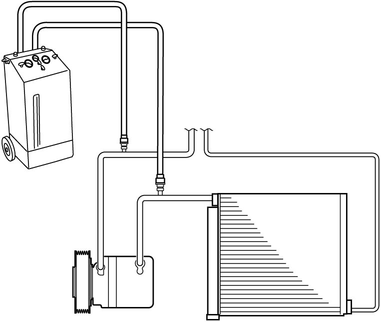
When discharging refrigerant out of A/C system, always recover it using refrigerant recovery and recycling equipment because discharging refrigerant HFC-134a (R-134a) into atmosphere would cause adverse effect to environment.
NOTE:
•After recovering refrigerant from system, measure the amount of removed compressor oil to determine the amount of compressor oil for replenishment.
•When handling recovery and recycling equipment, follow the instruction manual for the equipment.
•When handling recovery and recycling equipment, follow the instruction manual for the equipment.
HFO-1234yf model
When discharging refrigerant out of A/C system, always recover it using refrigerant recovery and recycling equipment because discharging refrigerant HFO-1234yf (R-1234yf) into atmosphere would cause adverse effect to environment.
NOTE:
•After recovering refrigerant from system, measure the amount of removed compressor oil to determine the amount of compressor oil for replenishment.
•When handling recovery and recycling equipment, follow the instruction manual for the equipment.
•When handling recovery and recycling equipment, follow the instruction manual for the equipment.
Replenishing compressor oil
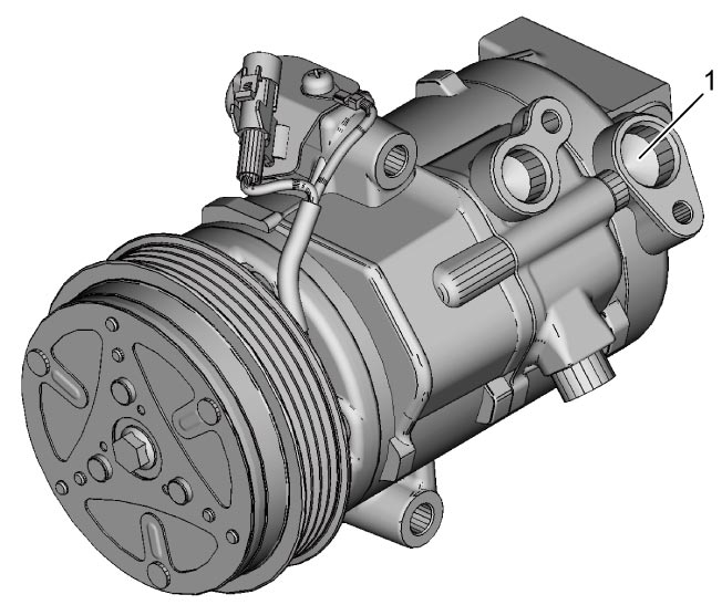
It is necessary to replenish compressor with specified amount of compressor oil from compressor suction side hole (1) before evacuating system and charging it with refrigerant.
When charging refrigerant only
When charging refrigerant without replacing any component, replenish compressor with compressor oil of the same amount measured when recovering refrigerant. If lost oil is not measured, add 30 cm3 (30 ml, 1.02 US.oz, 1.05 Imp.oz) of oil.
When replacing compressor
NOTICE:
Use of a compressor oil other than the specified oil is inappropriate for the components of the A/C system and may cause problems with operation of the system.
Use only the specified compressor oil or equivalent.
Compressor oil is sealed in each new compressor by the amount required for A/C system. Therefore, when using a new compressor, drain the calculated amount of oil from it.
“C” = “A” – “B”
“C”: Amount of oil to be drained
“A”: Amount of oil in a new compressor
“B”: Amount of oil in removed compressor
NOTE:
Compressor assembly supplied from factory is filled up with the following amount of oil.
Amount of oil in compressor
70 – 80 cm3 (70 – 80 ml, 2.37 – 2.70 US.oz, 2.47 – 2.81 Imp.oz)
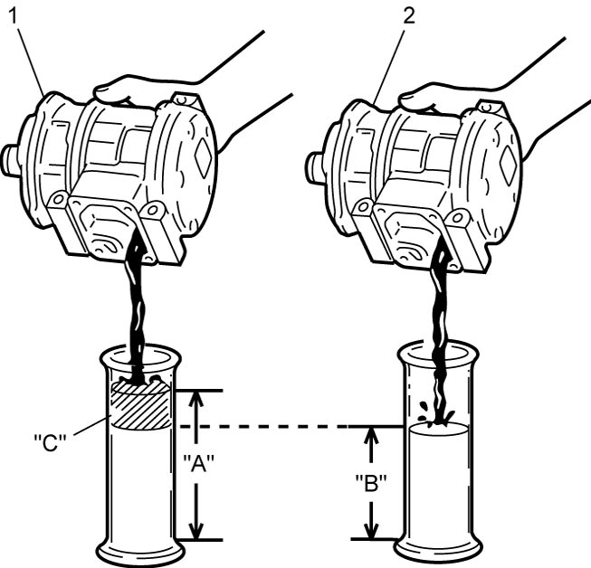
| 1. | New compressor | 2. | Removed compressor |
When replacing other parts
Replenish compressor with the following amount of oil.
Amount of compressor oil to be replenished
Evaporator: 15 cm3 (15 ml, 0.51 US.oz, 0.53 Imp.oz)
Condenser (with receiver/dryer): 20 cm3 (20 ml, 0.68 US.oz, 0.70 Imp.oz)
Hoses: 5 cm3 (5 ml, 0.17 US.oz, 0.18 Imp.oz) each
Pipes: 5 cm3 (5 ml, 0.17 US.oz, 0.18 Imp.oz) each
Evacuation
NOTICE:
Attempting to evacuate the A/C system when refrigerant remains in the system will damage the vacuum pump.
Do not evacuate the A/C system before completely recovering the refrigerant from the system.
NOTE:
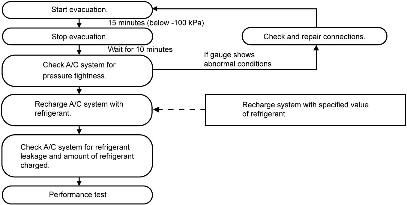
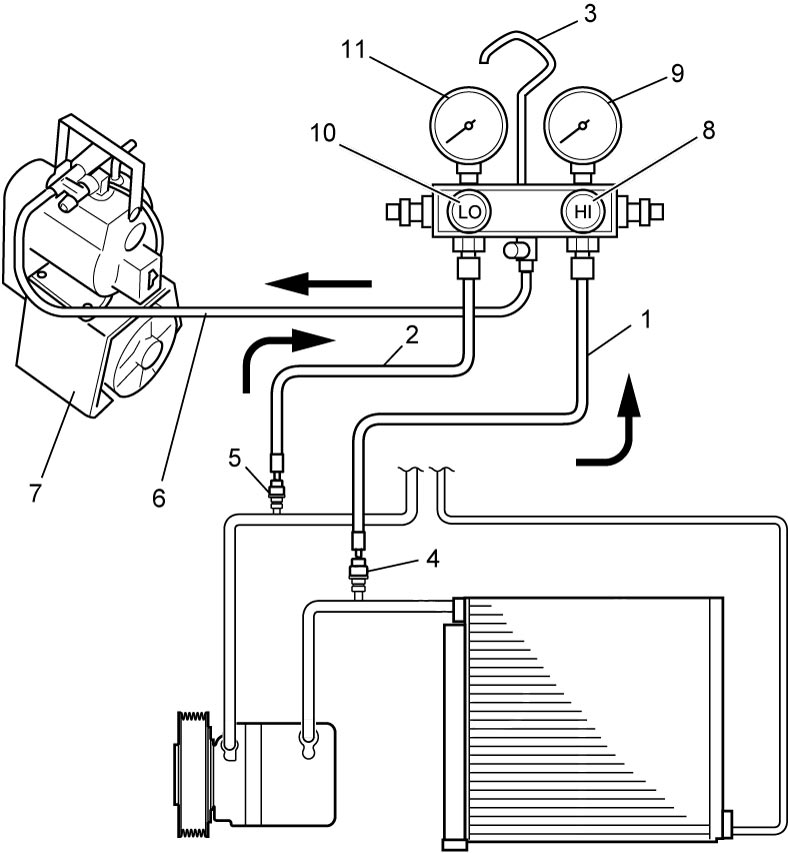
If A/C system circuit is opened (exposed) to atmosphere, system must be evacuated using a vacuum pump. The A/C system should be fitted with manifold gauge set, and should be evacuated for approximately 15 minutes.
1)Connect high pressure charging hose (1) and low pressure charging hose (2) of manifold gauge set (3) as follows:
High pressure charging hose → High pressure charging valve (4) on discharge hose
Low pressure charging hose → Low pressure charging valve (5) on suction pipe
High pressure charging hose → High pressure charging valve (4) on discharge hose
Low pressure charging hose → Low pressure charging valve (5) on suction pipe
2)Attach center charging hose (6) of manifold gauge set to vacuum pump (7).
3)Operate vacuum pump, and then open discharge side valve (HI) (8) of manifold gauge set.
If there is no blockage in the system, there will be an indication on high pressure gauge (9).
When this occurs, open the other side valve (LO) (10) of the gauge set.
If there is no blockage in the system, there will be an indication on high pressure gauge (9).
When this occurs, open the other side valve (LO) (10) of the gauge set.
4)Approximately 10 minutes later, low pressure gauge (11) should show a vacuum lower than –100 kPa (–1.0 kgf/cm2, –760 mmHg, –14.7 psi), indicating that no leakage exists.
NOTE:
•If the system does not show a vacuum below –100 kPa (–1.0 kgf/cm2, –760 mmHg, –14.7 psi), close both valves, stop vacuum pump and watch change in reading of low pressure gauge.
•Increase in gauge reading suggests of leakage. In this case, repair the system before continuing its evacuation.
•If the gauge shows a stable reading (suggesting no leakage), continue evacuation.
•Increase in gauge reading suggests of leakage. In this case, repair the system before continuing its evacuation.
•If the gauge shows a stable reading (suggesting no leakage), continue evacuation.
5)Carry out evacuation for a total of at least 15 minutes.
6)Continue evacuation until lower pressure gauge indicates a vacuum less than –100 kPa (–1.0 kgf/cm2, –760 mmHg, –14.7 psi), and then close both valves.
7)Stop vacuum pump. Disconnect center charging hose from pump inlet. Now, the system is ready for charging refrigerant.
Checking A/C system for pressure leakage
After completing the evacuation, close manifold gauge high pressure valve and low pressure valve and wait for 10 minutes. Check that low pressure gauge reading has not changed.
NOTE:
If gauge reading moves closer to “0”, there is leakage somewhere. Check the tubing connections and make necessary corrections.
Then, evacuate system once again and check that there is no leakage.
Charge
HFC-134a model
 WARNING:
There is a risk of personal injury or health problems if the A/C system is charged with refrigerant incorrectly or if refrigerant containers are improperly handled.
Take the following precautions to reduce the risk of injury or health problems.
•Perform the refrigerant charge operation with the engine stopped. Charge the high-pressure side first and then the low-pressure side. If you do not, the refrigerant may flow backward and cause the hose or refrigerant container to burst.
•Install the tap valve carefully following the instructions on the refrigerant container to prevent contact with the refrigerant.
•Empty the refrigerant container before discarding it to prevent possible health problems and other dangerous consequences.
•Never expose the refrigerant container to a heat higher than 40 °C (104 °F). Liquid refrigerant will turn into a toxic gas.
•Install the tap valve carefully following the instructions on the refrigerant container to prevent contact with the refrigerant.
•Empty the refrigerant container before discarding it to prevent possible health problems and other dangerous consequences.
•Never expose the refrigerant container to a heat higher than 40 °C (104 °F). Liquid refrigerant will turn into a toxic gas.
NOTICE:
Failure to take proper precautions when charging the A/C system can result in charging the system with the incorrect amount of refrigerant and can lead to poor system operation or damage to system components.
•Since the A/C system has no sight glass, first recover refrigerant and evacuate the system, and then fill the system with the specified amount of refrigerant.
•Charge the system only when the compressor is not hot to assure that you have used the correct amount of refrigerant.
•Check the pressure gauges before and during charging to assure that there is the correct amount of refrigerant in the system.
•Do not turn the refrigerant container upside down during charging. Doing so will cause liquid refrigerant to enter the compressor and damage it.
•Charge the system only when the compressor is not hot to assure that you have used the correct amount of refrigerant.
•Check the pressure gauges before and during charging to assure that there is the correct amount of refrigerant in the system.
•Do not turn the refrigerant container upside down during charging. Doing so will cause liquid refrigerant to enter the compressor and damage it.
NOTE:
The A/C system contains HFC-134a (R-134a).
Described here is a method for charging the A/C system with refrigerant from the refrigerant service container.
When charging the system with the refrigerant recovered using the refrigerant recycling equipment, follow the procedure described in the equipment manufacturer’s instruction manual.
Perform initial charge through high pressure side with the engine stopped.
Next, charge the system with refrigerant as follows from low pressure side with engine running.
1)Check if hoses are routed properly after evacuating system.
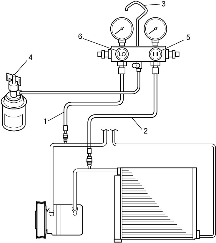
2)Connect low charging hose (1) and high charging hose (2) of manifold gauge set (3) in position. Then, open refrigerant container valve (4) to purge charging line.
3)Open high pressure side valve (5) to charge system with refrigerant.
4)After a while, open low pressure side valve (6) and close high pressure side valve.
WARNING:
WARNING:
If the high-pressure side valve is not closed securely, the refrigerant may flow backwards and cause the hose or refrigerant container to burst, possibly resulting in a personal injury.
Close the high-pressure side valve securely.
5)Start engine and keep engine speed at 1500 r/min, and then operate A/C system.
6)Charge A/C system with vapor refrigerant. At this time, refrigerant container should be held upright.

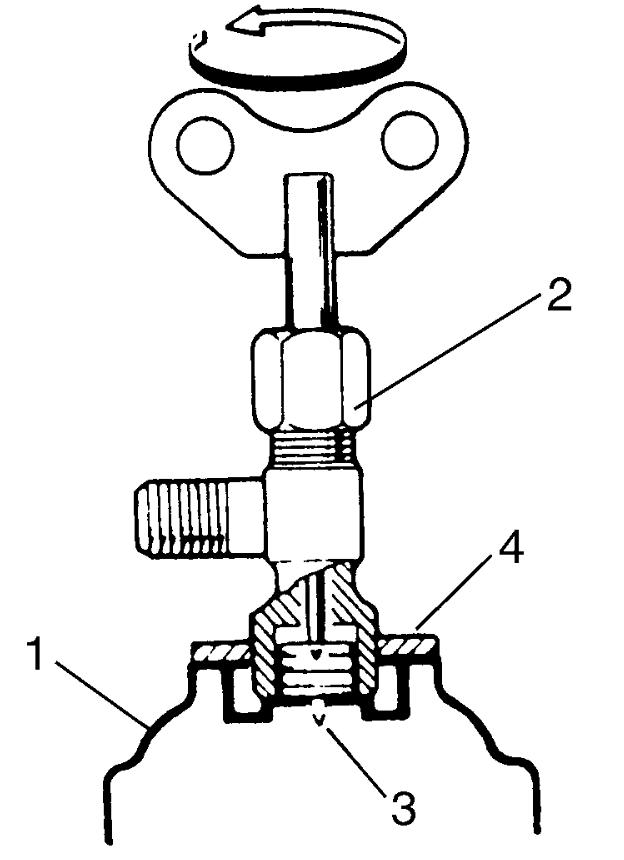
7)When refrigerant container (1) is emptied, use the following procedure to replace it with a new refrigerant container.
a)Close low pressure valve.
b)Replace empty container with a refrigerant container which has been charged with refrigerant. When using refrigerant container tap valve (2), use the following procedure for replacement.
i)Turn handle of tap valve counterclockwise to retract needle (3), and then remove refrigerant container tap valve by loosening its plate nut (4).
ii)Install refrigerant container tap valve to new refrigerant container.
c)Purge any air from center charging hose.
When using refrigerant container tap valve, use the following procedure to purge air.
When using refrigerant container tap valve, use the following procedure to purge air.
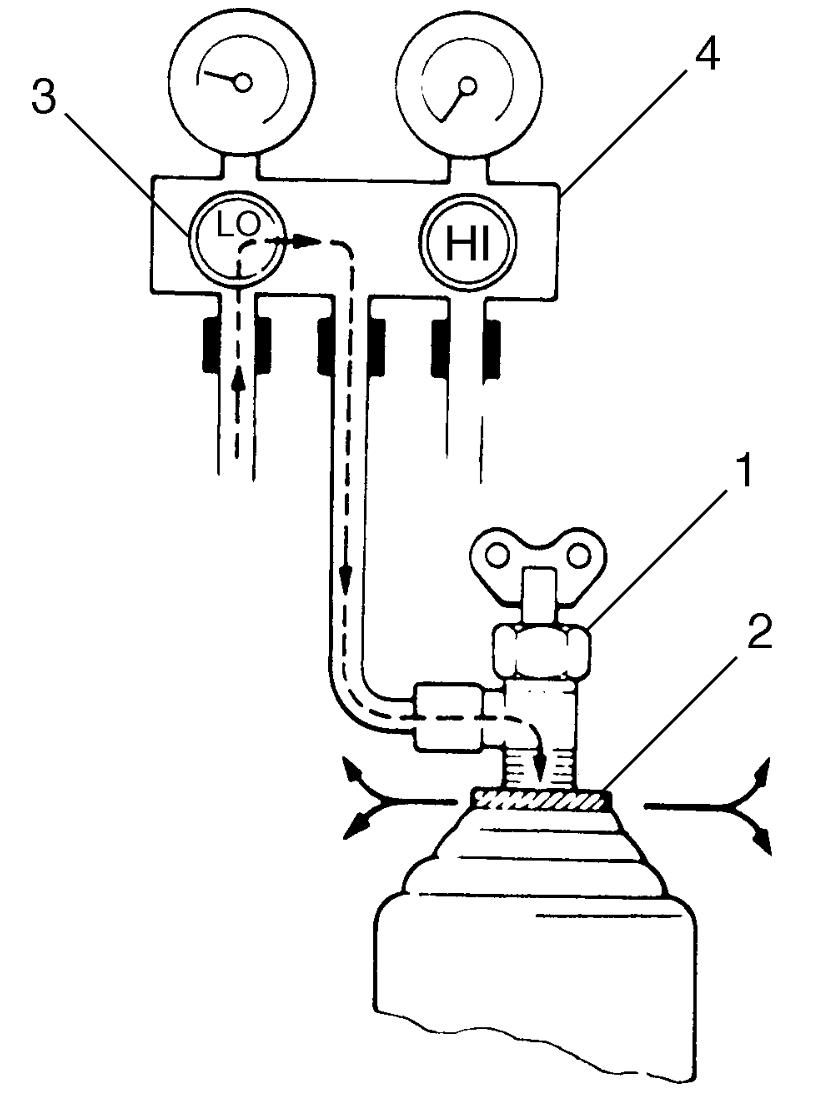
i)Fully tighten refrigerant container tap valve (1), and then loosen (open) plate nut (2) slightly.
ii)Open low pressure side valve (3) of manifold gauge set (4) a little.
iii)As soon as refrigerant comes out with a “hiss” through a clearance between refrigerant container and tap valve, tighten plate nut as well as low pressure side valve.
iv)Turn handle of tap valve clockwise so that its needle is screwed into the new container to make a hole for refrigerant flow.
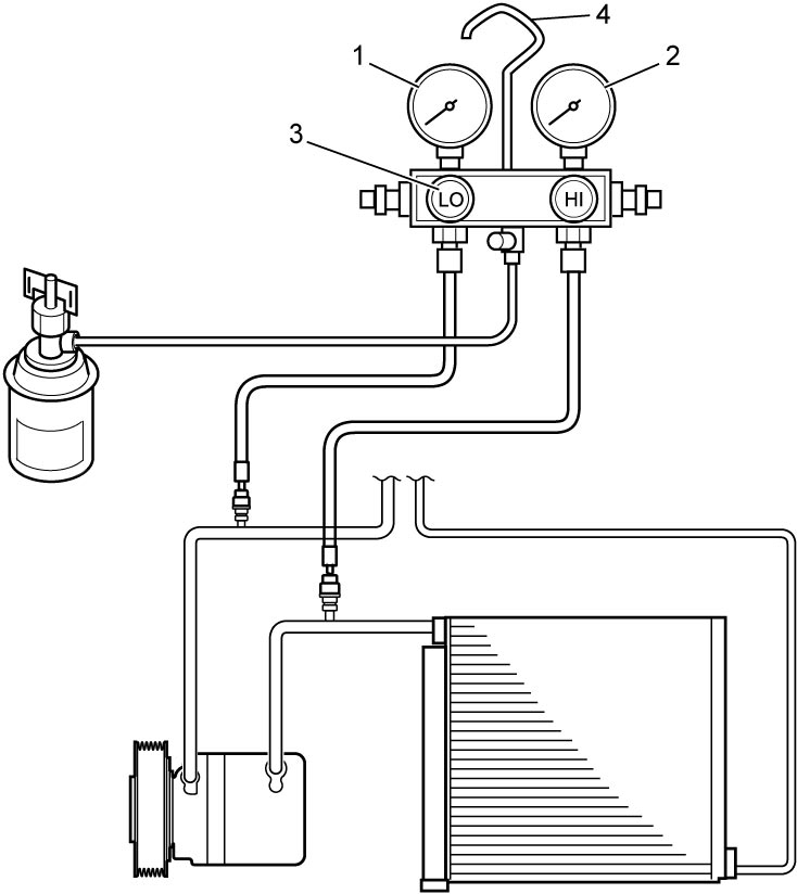
8)After the system is charged with specified amount of refrigerant or when low pressure gauge (1) and high pressure gauge (2) have indicated the following specified values, close low pressure side valve (3) on manifold gauge set (4).
Specified amount of refrigerant
400 ± 20 g (14.1 ± 0.7 oz)
Low pressure side and high pressure side example
| Gauges should read as follows when ambient temperature is 30 °C (86 °F). | |
| Pressure on high pressure gauge | 1300 – 2090 kPa (13.3 – 21.3 kgf/cm2) (188 – 303 psi) |
| Pressure on low pressure gauge | 190 – 290 kPa (2.0 – 2.9 kgf/cm2) (27.5 – 42.0 psi) |
HFO-1234yf model
WARNING:
There is a risk of personal injury or health problems if the A/C system is charged with refrigerant incorrectly or if refrigerant containers are improperly handled.
Take the following precautions to reduce the risk of injury or health problems.
•Perform the refrigerant charge operation with the engine stopped. Charge the high-pressure side first and then the low-pressure side. If you do not, the refrigerant may flow backward and cause the hose or refrigerant container to burst.
•Install the tap valve carefully following the instructions on the refrigerant container to prevent contact with the refrigerant.
•Empty the refrigerant container before discarding it to prevent possible health problems and other dangerous consequences.
•Never expose the refrigerant container to a heat higher than 40 °C (104 °F). Liquid refrigerant will turn into a toxic gas.
•Install the tap valve carefully following the instructions on the refrigerant container to prevent contact with the refrigerant.
•Empty the refrigerant container before discarding it to prevent possible health problems and other dangerous consequences.
•Never expose the refrigerant container to a heat higher than 40 °C (104 °F). Liquid refrigerant will turn into a toxic gas.
NOTICE:
Failure to take proper precautions when charging the A/C system can result in charging the system with the incorrect amount of refrigerant and can lead to poor system operation or damage to system components.
•Since the A/C system has no sight glass, first recover refrigerant and evacuate the system, and then fill the system with the specified amount of refrigerant.
•Charge the system only when the compressor is not hot to assure that you have used the correct amount of refrigerant.
•Check the pressure gauges before and during charging to assure that there is the correct amount of refrigerant in the system.
•Do not turn the refrigerant container upside down during charging. Doing so will cause liquid refrigerant to enter the compressor and damage it.
•Charge the system only when the compressor is not hot to assure that you have used the correct amount of refrigerant.
•Check the pressure gauges before and during charging to assure that there is the correct amount of refrigerant in the system.
•Do not turn the refrigerant container upside down during charging. Doing so will cause liquid refrigerant to enter the compressor and damage it.
NOTE:
The A/C system contains HFO-1234yf (R-1234yf).
Described here is a method for charging the A/C system with refrigerant from the refrigerant service container.
When charging the system with the refrigerant recovered using the refrigerant recycling equipment, follow the procedure described in the equipment manufacturer’s instruction manual.
Perform initial charge through high pressure side with the engine stopped.
Next, charge the system with refrigerant as follows from low pressure side with engine running.
1)Check if hoses are routed properly after evacuating system.
2)Connect low charging hose (1) and high charging hose (2) of manifold gauge set (3) in position. Then, open refrigerant container valve (4) to purge charging line.
3)Open high pressure side valve (5) to charge system with refrigerant.
4)After a while, open low pressure side valve (6) and close high pressure side valve.
WARNING:
WARNING:
If the high-pressure side valve is not closed securely, the refrigerant may flow backwards and cause the hose or refrigerant container to burst, possibly resulting in a personal injury.
Close the high-pressure side valve securely.
5)Start engine and keep engine speed at 1500 r/min, and then operate A/C system.
6)Charge A/C system with vapor refrigerant. At this time, refrigerant container should be held upright.
7)When refrigerant container (1) is emptied, use the following procedure to replace it with a new refrigerant container.
a)Close low pressure valve.
b)Replace empty container with a refrigerant container which has been charged with refrigerant. When using refrigerant container tap valve (2), use the following procedure for replacement.
i)Turn handle of tap valve counterclockwise to retract needle (3), and then remove refrigerant container tap valve by loosening its plate nut (4).
ii)Install refrigerant container tap valve to new refrigerant container.
c)Purge any air from center charging hose.
When using refrigerant container tap valve, use the following procedure to purge air.
When using refrigerant container tap valve, use the following procedure to purge air.
i)Fully tighten refrigerant container tap valve (1), and then loosen (open) plate nut (2) slightly.
ii)Open low pressure side valve (3) of manifold gauge set (4) a little.
iii)As soon as refrigerant comes out with a “hiss” through a clearance between refrigerant container and tap valve, tighten plate nut as well as low pressure side valve.
iv)Turn handle of tap valve clockwise so that its needle is screwed into the new container to make a hole for refrigerant flow.
8)After the system is charged with specified amount of refrigerant or when low pressure gauge (1) and high pressure gauge (2) have indicated the following specified values, close low pressure side valve (3) on manifold gauge set (4).
Specified amount of refrigerant
470 ± 20 g (16.6 ± 0.7 oz)
Low pressure side and high pressure side example
| Gauges should read as follows when ambient temperature is 30 °C (86 °F). | |
|---|---|
| Pressure on high pressure gauge | 1300 – 2040 kPa (13.3 – 20.8 kgf/cm2) (188 – 295 psi) |
| Pressure on low pressure gauge | 220 – 340 kPa (2.3 – 3.4 kgf/cm2) (31.9 – 49.3 psi) |
Removal of manifold gauge set
WARNING:
If the manifold gauge set is removed carelessly, refrigerant under pressure may spray out of the high-pressure side of the A/C system. The refrigerant could contact your eyes or skin, causing injury.
Remove the manifold gauge set carefully, following the instructions provided below.
For A/C system charged with specified amount of refrigerant, remove manifold gauge set as follows:
1)Close low pressure side valve of manifold gauge set. (high pressure side valve has already been closed during charging process.)
2)Close refrigerant container valve.
3)Stop engine.
4)Using shop rag, remove charging hoses from service valves. Perform this operation quickly.
5)Put caps on service valves.
Checking A/C system for refrigerant leakage
Whenever refrigerant leakage is suspected in the system or any service operation has been performed which may result in malfunction of lines and connections, it is important to perform check for leakage.
Common sense should be used during refrigerant leakage test, since the need and extent of any such test will, in general, depend upon the nature of a complaint and the type of a service performed on the system.
Liquid leak detector
WARNING:
If the refrigerant is exposed to a fire, it turns to a poisonous gas (phosgene).
Do not inhale the gas that is produced if refrigerant is exposed to a fire.
There is a number of fittings and places throughout the A/C system where liquid leak detector solution may be used to pinpoint refrigerant leakage.
By applying the solution to the area in question with a swab, bubbles will form within seconds if there is leakage.
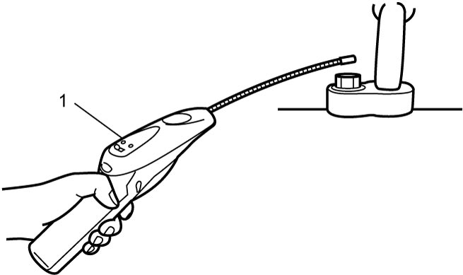
For connections in such confined areas, as those around evaporator and condenser, electronic (refrigerant) leak detector (1) is more practical for determining leakage.
NOTE:
The HVAC system of this vehicle uses either of two refrigerant types, HFC-134a or HFO-1234yf. Use leak detector compatible with respective refrigerant.