Headlight Aiming and Light Intensity Check
Precautions: Precautions for Headlight Auto Leveling System Service · Precautions for Body, Cab and Accessories · General safety (00)
NOTE:
•Unless otherwise required by local regulations, perform headlight aiming using either of the procedures described below.
•After any of the following services, aim headlights.
•After any of the following services, aim headlights.
—Headlight bulb replacement (halogen headlight model)
—Headlight unit removal and installation
—Headlight unit removal and installation
Preparation
1)Adjust air pressure of all tires to specified value.
2)Remove any load from vehicle.
3)Have one person of 75 kg (165 lb) sit on driver seat.
4)Start engine to fully charge battery.
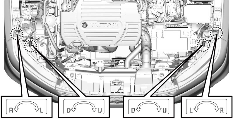
Aiming Adjustment Screw
Use aiming adjustment screws as shown in figure.
Procedure Using Tester
Follow tester manufacturer’s instructions.
Procedure Using Adjustment Screen
1)Prepare aiming screen as shown in figure.
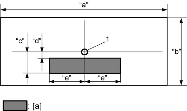

| [a]: | Elbow point adjustment range | “d”: | 20 mm (0.8 in.) |
| “a”: | About 420 mm (16.5 in.) | “e”: | 270 mm (10.6 in.) |
| “b”: | About 350 mm (13.8 in.) | 1. | Light center (Make a ø 10 mm (ø 0.4 in.) hole.) |
| “c”: | 150 mm (5.91 in.) |
2)Park vehicle on a level floor with vehicle front facing vertical wall (1).
3)Put a mark (3) on wall at the same height as headlight center position (2).
4)Align light center hole made in screen (4) with mark on wall and fix screen with its horizontal edges parallel with floor surface.
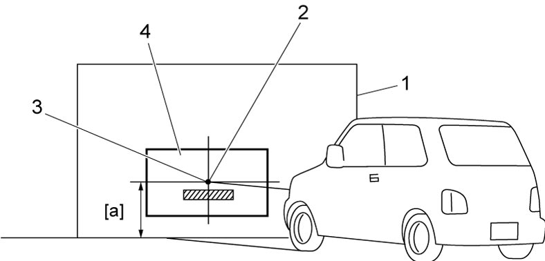
| [a]: | Headlight center height |
5)Locate vehicle 10 m (33 ft) away from screen (1) with its front directly against screen ([a] = [b]).
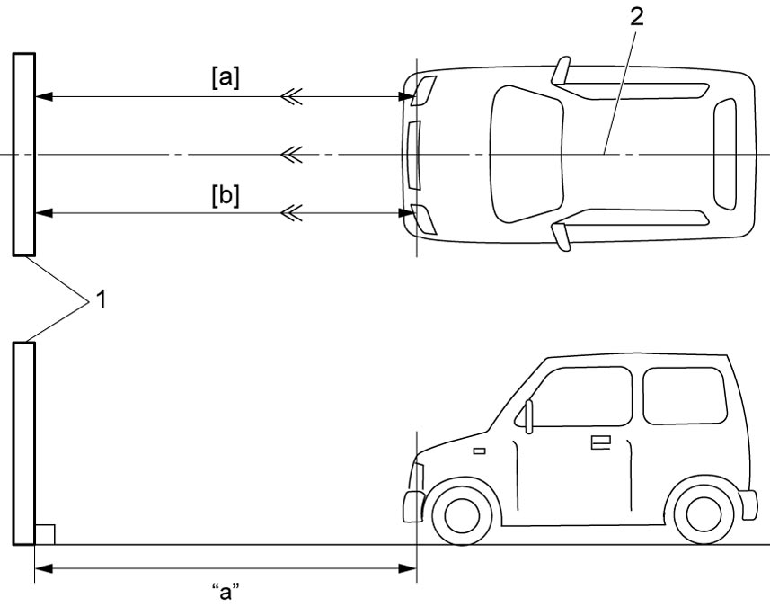
| “a”: | 10 m (33 ft.) | 2. | Vehicle center |
6)Block light from headlight not being adjusted by placing light shield in front of the light.
7)Turn on headlights (low beams).
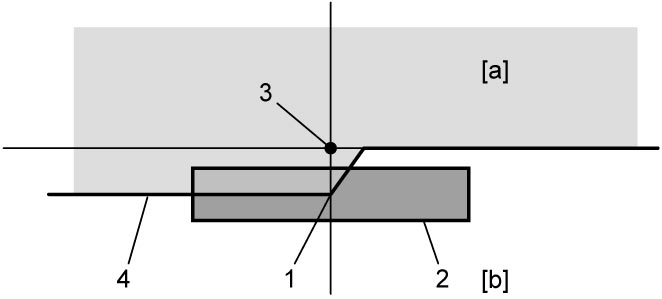
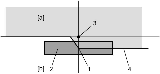
8)Adjust aiming screw so that elbow point (1) of low beam on screen is within adjustment range (2) as shown in figure.
•LHD:
•RHD:
| [a]: | Dark portion | 3. | Headlight center |
| [b]: | Bright portion | 4. | Bright / dark boundary |
| [a]: | Dark portion | 3. | Headlight center |
| [b]: | Bright portion | 4. | Bright / dark boundary |
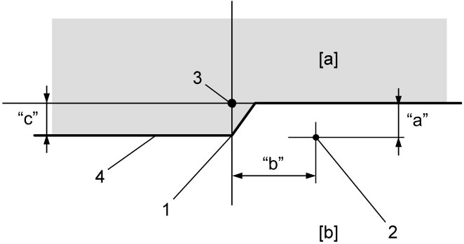
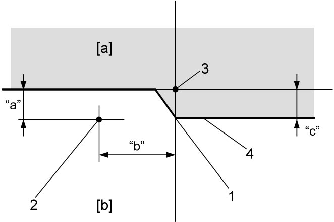
9)Check that light intensity measured on screen at a point 110 mm (4.33 in.) below and 230 mm (9.05 in.) to right of light center is at or higher than specified value.
•LHD:
•RHD:
| [a]: | Dark portion | 1. | Elbow point |
| [b]: | Bright portion | 2. | Brightness measurement point |
| “a”: | 110 mm (4.33 in.) | 3. | Headlight center |
| “b”: | 230 mm (9.05 in.) | 4. | Bright / dark boundary |
| “c”: | 130 mm (5.12 in.) |
| [a]: | Dark portion | 1. | Elbow point |
| [b]: | Bright portion | 2. | Brightness measurement point |
| “a”: | 110 mm (4.33 in.) | 3. | Headlight center |
| “b”: | 230 mm (9.05 in.) | 4. | Bright / dark boundary |
| “c”: | 130 mm (5.12 in.) |