Parking Sensor System Description (If Equipped)
Precautions: Precautions for Body, Cab and Accessories · General safety (00)
•The parking sensor system consists of the parking sensor system control module, combination meter (information display), front parking sensors (if equipped), rear parking sensors, parking sensor front buzzer (if equipped), parking sensor rear buzzer, parking sensor OFF switch, back up light switch (M/T model), and back up light relay (A/T model and twin clutch system model).
•The parking sensor system activates illuminating indicator light when the parking sensor OFF switch is pressed (ON) and:
•The parking sensor system control module communicates with the combination meter via the LIN communication system. (For LIN communication, refer to Communication System Description:M16A Model or Communication System Description:D16AA Model or Communication System Description:K14C Model.)
•DTC for parking sensor control system can be checked by selecting the “Combination Meter / Meter/M&A” on SUZUKI scan tool.
•The parking sensor system activates illuminating indicator light when the parking sensor OFF switch is pressed (ON) and:
—The shift position is in “N”, “D”, or “M” range (A/T model and twin clutch system model) with the vehicle speed approx. 10 km/h (6 mile/h) or lower.
—The shift position is in “R” range.
•If the parking sensors located on the front and rear bumpers detect an obstacle, the parking sensor system control module causes a symbol representing the direction of and distance to the obstacle to be indicated on the information display, in addition to causing the parking sensor buzzer to sound.—The shift position is in “R” range.
•The parking sensor system control module communicates with the combination meter via the LIN communication system. (For LIN communication, refer to Communication System Description:M16A Model or Communication System Description:D16AA Model or Communication System Description:K14C Model.)
•DTC for parking sensor control system can be checked by selecting the “Combination Meter / Meter/M&A” on SUZUKI scan tool.
Parking Sensor System Operating Condition
| Gear shift lever position | M/T | A/T, twin clutch system | Parking brake | |||
|---|---|---|---|---|---|---|
| R | N, 1st – 5th or 6th | R | N, D, M | |||
| Front sensor (if equipped) | Center | Off | On | Off | On | Off |
| Corner | On | On | On | On | No relation | |
| Rear sensor | Center | On | Off | On | Off | No relation |
| Corner | On | Off | On | Off | No relation | |
Information Display Indications and Buzzer Sounding Patterns
Obstacle detection by center-left / center-right parking sensor (Figures below represent indications when center-right parking sensor detects obstacle.)
Information display indication |
Front |
 |
 |
 |
|
Rear |
 |
 |
 |
||
Detection distance (reference) mm (in.) |
Front |
About 600 – 1,000 (23.6 – 39.4) |
About 450 – 600 (17.7 – 23.5) |
About 350 – 450 (13.8 – 17.6) |
About 350 or less (13.8) |
Rear |
About 600 – 1,500 (23.6 – 59.1) |
About 450 – 600 (17.7 – 23.5) |
About 350 – 450 (13.8 – 17.6) |
About 350 or less (13.8) |
|
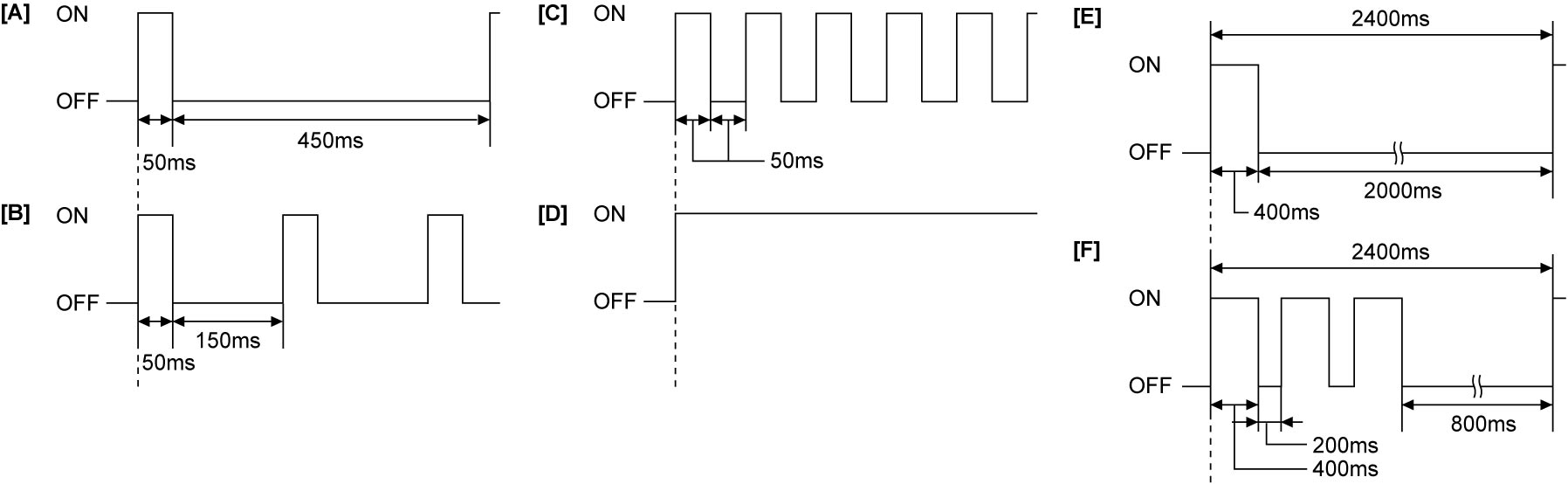
Buzzer sounding pattern |
[A] | [B] | [C] | [D] | |
Obstacle detection by left / right parking sensor (Figures below represent indications when right parking sensor detects obstacle.)
Information display indication |
Front |
 |
 |
 |
Rear |
 |
 |
 |
|
Detection distance (reference) mm (in.) |
About 450 – 600 (17.7 – 23.6) |
About 350 – 450 (13.8 – 17.6) |
About 350 or less (13.8) |
|
Buzzer sounding pattern |
[B] | [C] | [D] | |
Parking sensor malfunction warnings (Figures below represent warnings for malfunctions related to center parking sensors.)
Information display indication |
Front |
|
|
 |
| (Flashing) | (Flashing) | (Flashing) | ||
Rear |
|
|
 |
|
| (Flashing) | (Flashing) | (Flashing) | ||
Faulty condition (reference) |
Temporarily detected parking sensor malfunction | Continuously detected parking sensor malfunction | Fault in communication bus between parking sensor(s) and parking sensor system control module | |
Buzzer sounding pattern |
[E] | [F] | [E] (temporary detection) [F] (continuous detection) |
|