DTC P1311 / P1312
Precautions: Precautions for Diagnosing Trouble · Precautions for Servicing ENG A-STOP System · Precautions for Replacing ENG A-STOP Control Module · Precautions for Control Systems · General safety (00)
DTC Detecting Condition and Trouble Area
| DTC detecting condition | Trouble area |
|---|---|
|
P1311: ENG A-STOP Starter Relay Circuit Low Measured voltage of ST2 relay drive circuit is not as specified for specified time continuously. |
•“ST” fuse
•ST2 relay circuit / connector •ST2 relay •ENG A-STOP control module |
|
P1312: ENG A-STOP Starter Relay Circuit High Measured voltage of ST2 relay drive circuit is not as specified for specified time continuously. |
Circuit Diagram
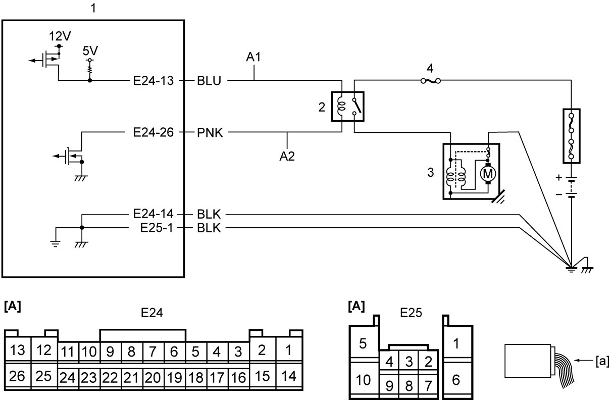
| [A]: | ENG A-STOP control module connector (View: [a]) | 1. | ENG A-STOP control module | 4. | “ST” fuse |
| A1: | ST2 relay drive circuit | 2. | ST2 relay | ||
| A2: | ST2 relay signal circuit | 3. | Starting motor |
DTC Confirmation Procedure
1)Set ignition “ON”.
DTC Troubleshooting
| Step | Action | Yes | No |
|---|---|---|---|
| 1 |
ST2 relay drive circuit and signal circuit check
1)Check that ignition is “OFF”.
2)Remove ST2 relay.
3)Disconnect “E24” connector.
4)Check for proper terminal connection to “E24” and ST2 relay connectors.
5)If connections are OK, check the following points.
•Resistance of “A1” and “A2” circuits: less than 1 Ω
•Resistance between each of “A1” and “A2” circuit and ground: infinity •Resistance between each of “A1” and “A2” circuit terminals and other terminal at ST2 relay connector: infinity •Voltage of “A1” and “A2” circuits: approx. 0 V (When ignition is “ON”) Is check result OK?
|
Go to Step 2.
|
Repair or replace defective wire harness.
|
| 2 |
ST2 relay check
1)Check ST2 relay.

Is check result OK?
|
Replace ENG A-STOP control module and recheck for DTC.
|
Replace ST2 relay.
|