DC/DC Converter Inspection (A/T Model)
Precautions: Precautions for Diagnosing Trouble · Precautions for Servicing ENG A-STOP System · Precautions for Replacing ENG A-STOP Control Module · Precautions for Control Systems · General safety (00)
Voltage and Signal Check
Check voltage of DC/DC converter (1) using voltmeter (2).
NOTE:
Check that battery voltage is 12 V or more.
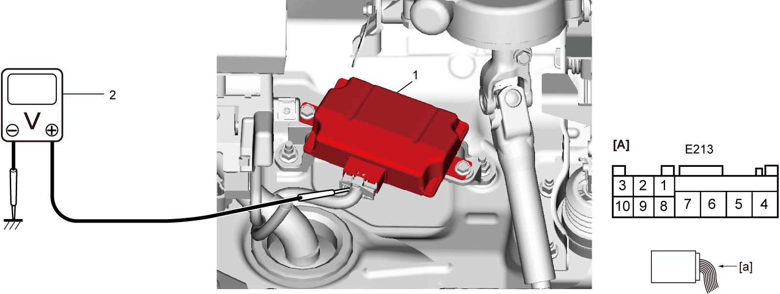
| [A]: | DC/DC converter connector (View: [a]) |
“E213” connector
| Terminal No. | Wire color | Circuit | Normal voltage | Condition |
|---|---|---|---|---|
| E213-1 | — | — | — | — |
| E213-2 | — | — | — | — |
| E213-3 | — | — | — | — |
| E213-4 | BRK | Ground for DC/DC converter | Approx. 0 V | — |
| E213-5 | GRN | DC/DC converter power supply | 10 – 14 V | — |
| E213-6 | — | — | — | — |
| E213-7 | WHT | DC/DC converter output | 10 – 14 V | Ignition: “ON” |
| Approx. 0 V | Other than above condition | |||
| E213-8 | WHT | Ignition “ON” signal | 10 – 14 V | Ignition: “ON” |
| Approx. 0 V | Other than above condition | |||
| E213-9 | PPL | DC/DC converter ON signal | Approx. 2 V | Ignition: “ON” |
| 4 – 6 V | During engine auto start control | |||
| Approx. 0 V | Other than above condition | |||
| E213-10 | YEL | DC/DC converter diagnosis signal | 10 – 14 V | Ignition: 1 sec. after ignition “OFF” |
| Approx. 0 V | Other than above condition |