| OK |  |
| VVT SYSTEM OK |
DTC P0011 Camshaft Position "A" - Timing Over-Advanced or System Performance (Bank 1) |
DTC P0012 Camshaft Position "A" - Timing Over-Retarded (Bank 1) |
DTC P0021 Camshaft Position "A" - Timing Over-Advanced or System Performance (Bank 2) |
DTC P0022 Camshaft Position "A" - Timing Over-Retarded (Bank 2) |
| DTC No. | DTC Detection Condition | Trouble Area |
| P0011 P0021 |
|
|
| P0012 P0022 |
|
| Related DTCs | P0011: Advance camshaft timing (bank 1) P0012: Retard camshaft timing (bank 2) P0021: Advance camshaft timing (bank 1) P0022: Retard camshaft timing (bank 2) |
| Required Sensors/Components (Main) | VVT OCV and VVT actuator |
| Required Sensors/Components (Related) | Engine Coolant Temperature sensor, Camshaft position sensor, Crankshaft position sensor |
| Frequency of Operation | Once per driving cycle |
| Duration | 10 seconds |
| MIL Operation | P0011 and P0021: Immediate P0012 and P0022: 2 driving cycles |
| Sequence of Operation | None |
| Monitor will run whenever these DTCs are not present | P0100 - P0103 (MAF sensor) P0115 - P0118 (ECT sensor) P0125 (Insufficient ECT for closed loop) P0335 (CKP sensor) P0351 - P0358 (igniter) |
| Battery voltage | 11 V or more |
| Engine RPM | 400 to 4,000 rpm |
| ECT | 75 to 100°C (167 to 212°F) |
| Both of the following conditions are met | - |
| (a) Deviation of valve timing | More than 5° CA (crankshaft angle) |
| (b) Valve timing | No change at advanced valve timing |
| Both of the following conditions are met | - |
| (a) Deviation of valve timing | More than 5° CA (crankshaft angle) |
| (b) Valve timing | No change at retarded valve timing |
| Abnormal bank | Advanced timing over (Valve timing is out of specified range) | Retarded timing over (Valve timing is out of specified range) |
| Bank 1 | P0011 | P0012 |
| Bank 2 | P0021 | P0022 |
| 1.PERFORM ACTIVE TEST BY INTELLIGENT TESTER (OCV OPERATION) |
Connect the intelligent tester to the CAN VIM. Then connect the CAN VIM to the DLC3.
Start the engine and warm it up.
Enter the following menus: DIAGNOSIS / ENHANCED OBD II / ACTIVE TEST / VVT CTRL B1 or VVT CTRL B2.
Using the intelligent tester, operate the Oil Control Valve (OCV) and check the engine speed.
| Tester Operation | Specified Condition |
| OCV is OFF | Normal engine speed |
| OCV is ON | Rough idle or engine stall |
|
| ||||
| NG | |
 |
| 2.CHECK VALVE TIMING (CHECK FOR LOOSE AND JUMPED TOOTH OF TIMING BELT) |
Check valve timing (Click here).
|
| ||||
| OK | |
|
| 3.CHECK HARNESS AND CONNECTOR (OCV-ECM) |
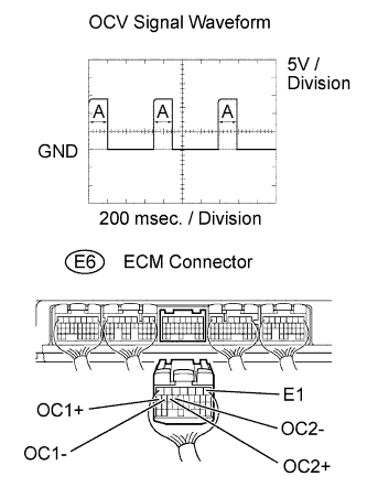 |
Inspection using the oscilloscope.
During idling, check the waveform between the specified terminals of the E6 ECM connector.
|
| ||||
| OK | |
|
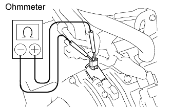
| 4.INSPECT CAMSHAFT TIMING OIL CONTROL VALVE ASSEMBLY |
 |
Remove the V-bank cover.
Remove the air cleaner inlet and intake air connector.
Disconnect the C13 and C14 Oil Control Valve (OCV) connectors.
Measure the resistance of the OCV.
Reconnect the OCV connector.
Reinstall the air cleaner inlet and intake air connector.
Reinstall the V-bank cover.
|
| ||||
| OK | |
|
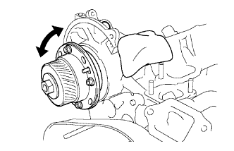
| 5.INSPECT VVT CONTROLLER ASSEMBLY |
 |
Remove the timing belt (Click here).
Remove the cylinder head cover.
Remove the OCV.
Drain the oil in the VVT controller assembly.
Check whether the oil in VVT controller assembly is drained or not.
Reinstall the OCV.
Reinstall the cylinder head cover.
Reinstall the timing belt.
|
| ||||
| NG | |
|
| 6.REPLACE VVT CONTROLLER ASSEMBLY |
| NEXT | |
|
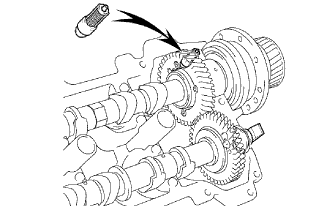
| 7.INSPECT OIL CONTROL VALVE FILTER |
 |
Remove the cylinder head cover .
Remove the camshaft bearing cap and OCV filter.
Check that the filter is not clogged.
Reinstall the camshaft bearing cap and OCV filter.
Reinstall the cylinder head cover.
|
| ||||
| OK | |
|
| 8.CHECK WHETHER DTC OUTPUT RECURS (DTC P0011, P0012, P0021 OR P0022) |
Connect the intelligent tester to the CAN VIM.
Then connect the CAN VIM to the DLC3.
Turn the ignition switch ON and turn the tester ON.
Clear DTCs.
Start the engine and warm it up.
Switch the ECM from normal mode to check mode using the tester.
Drive the vehicle for more than 10 minutes.
Read output DTCs using the tester.
|
| ||||
| NG | ||
 | ||
| ||
