Home › ENGINE ยท 2UZ-FE › ENGINE CONTROL SYSTEM › SFI SYSTEM

DTC    P0016    Crankshaft Position - Camshaft Position Correlation (Bank 1 Sensor A)

DTC    P0018    Crankshaft Position - Camshaft Position Correlation (Bank 2 Sensor A)

for Preparation Click here


DESCRIPTION

VVT sensor (VVL or VVR signal) consist of a signal plate and pickup coil.
The VVL or VVR signal plate has 1 tooth on its outer circumference and is mounted on the intake camshafts.
When the camshafts rotate, the protrusion on the signal plate and the air gap on the pickup coil change, causing fluctuations in the magnetic field and generating an electromotive force in the pickup coil.
The actual camshaft angle is detected by the VVT sensor and it provides feedback to the ECM to control the intake valve timing in response to during condition.

DTC No.
DTC Detection Condition
Trouble Area
P0016
P0018
  1. No VVT sensor signal to ECM during cranking at 4 sec. or more
  2. No VVT sensor signal to ECM with 5 sec. or more engine speed 600 rpm or more
  3. While the crankshaft rotates twice, VVT sensor signal will be input to ECM 5 times
  1. Open or short in VVT sensor circuit
  2. VVT sensor
  3. ECM

MONITOR DESCRIPTION

The ECM optimizes the valve timing by using the VVT (Variable Valve Timing) system to control the intake camshaft. The VVT system includes the ECM, the Oil Control Valve (OCV) and the VVT controller. The ECM sends a target duty-cycle control signal to the OCV. This control signal applied to the OCV, regulates the oil pressure supplied to the VVT controller. The VVT controller can advance or retard the intake valve camshaft. The ECM calibrates the intake valve timing by setting the intake camshaft to the most retarded angle while the engine is idling. The ECM closes the OCV to retard the cam. The ECM stores this value as the VVT learning value. When the difference between the target and actual intake valve timings is 5°CA (Crankshaft Angle) or less, the ECM stores it.
If the VVT learning value matches the following conditions, the ECM determines the existence of a malfunction in the VVT system, and sets the DTC.
  1. VVT learning value: Less than 20°CA (Crankshaft Angle), or more than 39°CA.
  2. Above condition continues for 18 seconds or more.

MONITOR STRATEGY


Related DTCs
P0016: Camshaft timing (bank 1) misalignment
P0018: Camshaft timing (bank 2) misalignment
Required Sensors/Components (Main)
VVT actuator
Required Sensors/Components (Related)
Camshaft position sensor, Crankshaft position sensor
Frequency of Operation
Once per driving cycle
Duration
Within 60 seconds
MIL Operation
2 driving cycles
Sequence of Operation
None

TYPICAL ENABLING CONDITIONS


Monitor will run whenever these DTCs are not present
P0011 (VVT system 1 - advance)
P0012 (VVT system 1 - retard)
P0021 (VVT system 2 - advance)
P0115 - P0118 (ECT sensor)
Engine speed
400 to 1,400 rpm

TYPICAL MALFUNCTION THRESHOLDS


One of the following conditions is met
Condition (a) or (b)
(a) VVT learning value at maximum retarded valve timing
Less than 22.5°CA (crankshaft angle)
(b) VVT learning value at maximum retarded valve timing
bank 1: More than 44°CA (crankshaft angle)
bank 2: More than 47.5°CA (crankshaft angle)

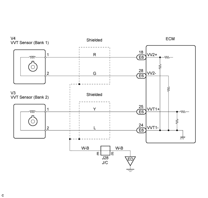
WIRING DIAGRAM


A130711E01


INSPECTION PROCEDURE

HINT:
  1. If DTC P0016 is displayed, check left bank VVT sensor.
  2. If DTC P0018 is displayed, check right bank VVT sensor.
  3. Read freeze frame data using the intelligent tester or OBD II scan tool. Because the ECU records vehicle and driving condition information as freeze frame data the moment a DTC is stored. When troubleshooting, freeze frame data can be helpful in determining whether the vehicle was running or stopped, whether the engine was warmed up or not, whether the air/fuel ratio was lean or rich, as well as other data recorded at the time of malfunction.

1.CHECK VALVE TIMING (CHECK FOR LOOSE AND JUMPED TOOTH OF TIMING BELT)
  1. Check valve timing (Click here).


NG
ADJUST VALVE TIMING
OK

REPLACE ECM