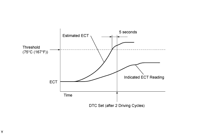
DTC P0128 Thermostat Malfunction |
| DTC No. | DTC Detection Condition | Trouble Area |
| P0128 |
|
|
| Related DTCs | P0128: Coolant thermostat |
| Required Sensors/Components (Main) | Thermostat, Engine cooling system |
| Required Sensors/Components (Related) | Engine coolant temperature sensor, Intake air temperature sensor, Vehicle speed sensor |
| Frequency of Operation | Once per drive cycle |
| Duration | 15 minutes |
| MIL Operation | 2 driving cycles |
| Sequence of Operation | None |
| Monitor will run whenever these DTCs are not present | P0010, P0020 (OCV Bank 1, 2) P0011 (VVT System 1 - Advance) P0012 (VVT System 1 - Retard) P0021 (VVT System 2 - Advance) P0022 (VVT System 2 - Retard) P0031, P0032, P0051, P0052 (A/F sensor heater - Sensor 1) P0100 - P0103 (MAF meter) P0110 - P0113 (IAT sensor) P0115 - P0118 (ECT sensor) P0125 (Insufficient ECT for closed loop) P0171, P0172 (Fuel system) P0300 - P0308 (Misfire) P0335 (CKP sensor) P0340, P0346 (VVT sensor 1, 2) P0351 - P0358 (igniter) P0500 (VSS) P2196, P2198 (A/F sensor - rationality) P2A00, P2A03 (A/F sensor - slow response) |
| Battery voltage | 11 V or higher |
| Throttle position learning | Completed |
| Either of the following conditions is met | Condition 1 or 2 |
| 1. All of the following conditions are met | Conditions (a), (b) and (c) |
| (a) ECT at engine start - IAT at engine start | -15 to 7°C (-27 to 12.6°F) |
| (b) ECT at engine start | -10 to 56°C (14 to 133°F) |
| (c) IAT at engine start | -10 to 56°C (14 to 133°F) |
| 2. All of the following conditions are met | Conditions (a), (b) and (c) |
| (a) ECT at engine start - IAT at engine start | More than 7°C (12.6°F) |
| (b) ECT at engine start | 56°C (133°F) or less |
| (c) IAT at engine start | -10°C (14°F) or more |
| Accumulated time that vehicle speed is 80 mph (128 km/h) or more | Less than 20 sec. |
| Duration that all of following conditions are met | 5 seconds or more |
| (a) Estimated ECT | 75°C (167°F) or higher |
| (b) ECT sensor voltage | Lower than 75°C (167°F) |
| MID | TID | Scaling | Description of Test Value | Minimum Test Limit | Maximum Test Limit |
| $E1 | $E8 | Multiply by 0.1 (°C) | ECT sensor output when estimated ECT reached to malfunction criteria | Malfunction criterion | Maximum test limit |
| 1.CHECK OTHER DTC OUTPUT (IN ADDITION TO DTC P0128) |
Connect the intelligent tester to the DLC3 with CAN VIM.
Turn the ignition switch ON and turn the intelligent tester ON.
Enter the following menus: DIAGNOSIS / ENHANCED II / DTC INFO / CURRENT CODES.
Read the DTC.
| Display (DTC Output) | Proceed to |
| P0128 | A |
| P0128 and other DTCs | B |
|
| ||||
| A | |
 |
| 2.CHECK COOLING SYSTEM |
Check for defects in the cooling system that might cause the system to be too cold, such as an abnormal radiator fan operation or a modified cooling system.
Check the valve opening temperature of the thermostat.
|
| ||||
| OK | |
|
| 3.INSPECT THERMOSTAT |
Remove the thermostat (Click here).
Check the valve opening temperature of the thermostat .
Reinstall the thermostat (Click here).
|
| ||||
| OK | ||
 | ||
| ||
