Home › DRIVE LINE ยท DIFFERENTIAL › DIFFERENTIAL SIDE GEAR SHAFT OIL SEAL (for 4WD)

DIFFERENTIAL SIDE GEAR SHAFT OIL SEAL (for 4WD) > INSTALLATION

for Preparation Click here


1. INSTALL DIFFERENTIAL SIDE GEAR SHAFT OIL SEAL


    C097018E01
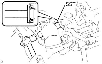
  1. Using SST and a hammer, install a new oil seal.

    SST
    09554-30011  

  1. Coat the oil seal lip with MP grease.


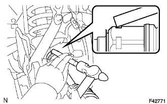
2. INSTALL FRONT DRIVE SHAFT ASSEMBLY LH


F042771
  1. Coat the spline of the inboard joint shaft assembly with ATF.

  1. Align the shaft splines and install the drive shaft with a brass bar and hammer.

    NOTICE:
    1. Set the snap ring with the opening side facing downward.
    2. Be careful not to damage the oil seal.

    HINT:
    Whether the inboard joint shaft is in contact with the pinion shaft or not can be confirmed from the sound or feeling when driving it.


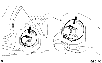
3. CONNECT NO. 1 FRONT SUSPENSION ARM SUB-ASSEMBLY LOWER LH


    G020160
  1. Fully tighten the bolt and the nut.

    Torque:
    135 N*m{ 1,380 kgf*cm , 100 ft.*lbf }


4. CONNECT TIE ROD END SUB-ASSEMBLY LH
  1. Connect the tie rod end to the steering knuckle arm.

  1. Install the nut and cotter pin.

    Torque:
    91 N*m{ 928 kgf*cm , 67 ft.*lbf }


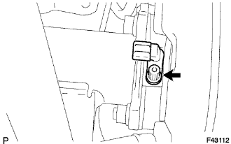
5. CONNECT FRONT SPEED SENSOR LH


    F043112
  1. Using a hexagon wrench (5 mm), install the front speed sensor with the bolt to the steering knuckle.
    SST
    99999-60011  

    Torque:
    8.3 N*m{ 85 kgf*cm , 73 in.*lbf }

    NOTICE:
    Make sure the sensor tip is clean.


    F044160
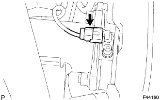
  1. Connect the speed sensor connector.


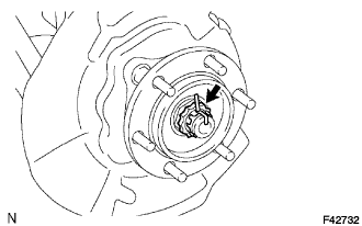
6. INSTALL FRONT AXLE HUB LH NUT


    F042732
  1. Install the hub nut.

    Torque:
    235 N*m{ 2,396 kgf*cm , 173 ft.*lbf }

  1. Install the adjusting cap and cotter pin.


7. FILL UP DIFFERENTIAL OIL


    D025304E03
  1. Stop the vehicle on a level place.

  1. Remove the differential filler plug and gasket.

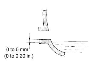
  1. Check that the oil level is within 5mm (0 to 0.20 in.) of the bottom of the filler plug opening.

    NOTICE:
    1. Excessively large or small quantities of oil may cause problems.
    2. After replacing the oil, drive the vehicle and check the oil level again.

    HINT:
    If necessary, fill the rear differential carrier assembly with hypoid gear oil.

    Oil grade:
    Hypoid gear oil API GL-5
    Recommended viscosity:
    Above -18°C (0°F) SAE 90
    Below -18°C (0°F) SAE 80W or 80W-90

    Capacity:
    Front differential carrier assembly:
    1.35 to 1.45 litters
    (1.43 to 1.53 US qts, 1.19 to 1.27 lmp. qts)
    Rear differential carrier assembly
    3.00 to 3.10 litters
    (3.17 to 3.27 US qts, 2.64 to 2.72 lmp. qts)

  1. Check for oil leakage if the oil level is low.

  1. Install the differential filler plug and a new gasket.

    Torque:
    Front differential carrier assembly:
    39 N*m{ 398 kgf*cm , 29 ft.*lbf }
    Rear differential carrier assembly:
    49 N*m{ 500 kgf*cm , 36 ft.*lbf }


8. INSPECT DIFFERENTIAL OIL


    D025304E03
  1. Stop the vehicle on a level place.

  1. Remove the differential filler plug and gasket.

  1. Check that the oil level is within 5mm (0 to 0.20 in.) of the bottom of the filler plug opening.

    NOTICE:
    1. Excessively large or small quantities of oil may cause problems.
    2. After replacing the oil, drive the vehicle and check the oil level again.

    HINT:
    If necessary, fill the rear differential carrier assembly with hypoid gear oil.

    Oil grade:
    Hypoid gear oil API GL-5
    Recommended viscosity:
    Above -18°C (0°F) SAE 90
    Below -18°C (0°F) SAE 80W or 80W-90

    Capacity:
    Front differential carrier assembly:
    1.35 to 1.45 litters
    (1.43 to 1.53 US qts, 1.19 to 1.27 lmp. qts)
    Rear differential carrier assembly
    3.00 to 3.10 litters
    (3.17 to 3.27 US qts, 2.64 to 2.72 lmp. qts)

  1. Check for oil leakage if the oil level is low.

  1. Install the differential filler plug and a new gasket.

    Torque:
    Front differential carrier assembly:
    39 N*m{ 398 kgf*cm , 29 ft.*lbf }
    Rear differential carrier assembly:
    49 N*m{ 500 kgf*cm , 36 ft.*lbf }


9. INSTALL NO. 1 ENGINE UNDER COVER SUB-ASSEMBLY
  1. Install the No. 1 engine under cover sub-assembly with the 4 bolts.


10. INSTALL ENGINE UNDER COVER ASSEMBLY REAR
  1. Install the engine under cover assembly with the 6 bolts.


11. INSTALL FRONT WHEEL

Torque:
112 N*m{ 1,142 kgf*cm , 83 ft.*lbf }


12. INSPECT ABS SPEED SENSOR SIGNAL

HINT:
(Click here)