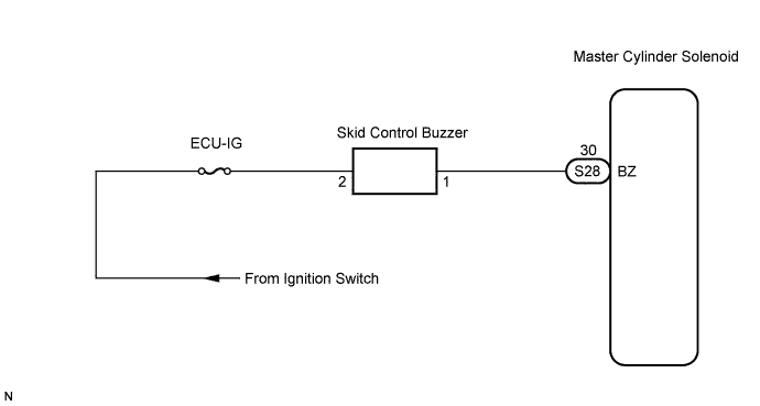
VEHICLE STABILITY CONTROL SYSTEM > Skid Control Buzzer Circuit |
| 1.PERFORM ACTIVE TEST BY INTELLIGENT TESTER (SKID CONTROL BUZZER) |
Connect the intelligent tester to the DLC3.
Turn the ignition switch to the ON position and push the intelligent tester main switch ON.
Select "ACTIVE TEST" mode on the intelligent tester.
| Item | Vehicle Condition / Test Details | Diagnostic note |
| VSC / BR WARN BUZ | Turns skid control buzzer ON /OFF | Buzzer can be heard |
Check that the buzzer sounds/stops when turning the skid control buzzer on/off by using the intelligent tester.
| Condition | Proceed to |
| Buzzer sounds/stops | A |
| Buzzer does not sound or sounds constantly | B |
|
| ||||
| B | |
 |
| 2.INSPECT SKID CONTROL BUZZER (POWER SOURCE TERMINAL) |
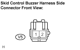 |
Disconnect the skid control buzzer connector.
Turn the ignition switch to the ON position.
Measure the voltage according to the value(s) in the table below.
| Tester Connection | Specified Condition |
| V5-2 - Body ground | 10 to 14 V |
|
| ||||
| OK | |
|
| 3.INSPECT SKID CONTROL BUZZER |
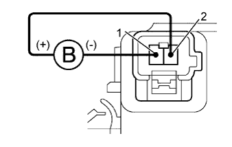 |
Apply battery negative voltage to terminal 1, and battery positive voltage to terminal 2 of the skid control buzzer, and then check that the buzzer sounds.
|
| ||||
| OK | |
|
| 4.CHECK HARNESS AND CONNECTOR (SKID CONTROL BUZZER - SKID CONTROL ECU) |
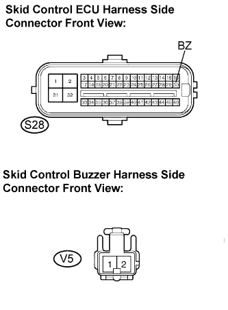 |
Disconnect the skid control ECU connector.
Measure the resistance according to the value(s) in the table below.
| Tester Connection | Specified Condition |
| S28-30 (BZ) - V5-1 | Below 1 Ω |
| S28-30 (BZ) - Body ground | 10 kΩ or higher |
|
| ||||
| OK | ||
 | ||
| ||
