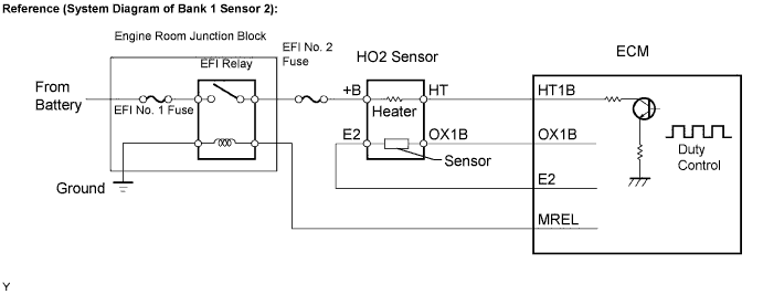
DTC P0037 Oxygen Sensor Heater Control Circuit Low (Bank 1 Sensor 2) |
DTC P0038 Oxygen Sensor Heater Control Circuit High (Bank 1 Sensor 2) |
DTC P0057 Oxygen Sensor Heater Control Circuit Low (Bank 2 Sensor 2) |
DTC P0058 Oxygen Sensor Heater Control Circuit High (Bank 2 Sensor 2) |
| DTC No. | DTC Detection Conditions | Trouble Areas |
| P0037 P0057 | Heated Oxygen (HO2) sensor heater current is less than 0.3 A (1 trip detection logic) |
|
| P0038 P0058 | Heated Oxygen (HO2) sensor heater current is more than 2 A (1 trip detection logic) |
|
| Related DTCs | P0037: Rear HO2S heater (Bank 1) range check (Low current) P0038: Rear HO2S heater (Bank 1) range check (High current) P0057: Rear HO2S heater (Bank 2) range check (Low current) P0058: Rear HO2S heater (Bank 2) range check (High current) |
| Required Sensors / Components (Main) | Heated oxygen sensor heater (bank 1 and 2) |
| Required Sensors / Components (Related) | Vehicle speed sensor (VSS) |
| Frequency of Operation | Continuous |
| Duration | 0.3 seconds |
| MIL Operation | Immediate |
| Sequence of Operation | None |
| Monitor runs whenever following DTCs not present | None |
| Battery voltage | 10.5 V or more |
| Engine | Running |
| Starter | OFF |
| Intrusive heating | Not operating |
| All heater is turned OFF and intrusive heating is operated when the following conditions are met | (a) and (b) |
| (a) Heater | ON |
| (b) Heater current | Less than 0.3 A |
| Battery voltage | 10.5 V or more |
| Engine | Running |
| Starter | OFF |
| Intrusive heating | Not operating |
| Battery voltage | 10.5 V or more |
| All heater is turned OFF and intrusive heating is operated when the following conditions are met | (a) and (b) |
| (a) Heater | ON |
| (b) Heater current | More than 2 A |
| Heated oxygen sensor heater current during intrusive heating | Less than 0.3 A |
| Heated oxygen sensor heater current | 2 A or more |
| Heated oxygen sensor heater current during intrusive heating | More than 2 A |
| Heated Oxygen (HO2) sensor heater current | 0.4 to 1 A (when engine idles, HO2 sensor warmed up and battery voltage 11 to 14 V) |
| TLT | CID | Unit Conversion | Description of Test Data | Description of Test Limit |
| 1 | $02 | Multiply by 0.000076 (A) | Maximum HO2S heater current (Bank 1 Sensor 2) | Malfunction threshold for HO2S heater |
| 1 | $04 | Multiply by 0.000076 (A) | Maximum HO2S heater current (Bank 1 Sensor 3) | Malfunction threshold for HO2S heater |
| 1 | $20 | Multiply by 0.000076 (A) | Maximum HO2S heater current (Bank 2 Sensor 2) | Malfunction threshold for HO2S heater |
| 1 | $40 | Multiply by 0.000076 (A) | Maximum HO2S heater current (Bank 2 Sensor 3) | Malfunction threshold for HO2S heater |
| 1.INSPECT HEATED OXYGEN SENSOR (HEATER RESISTANCE) |
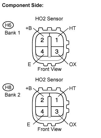 |
Disconnect the H6 or H8 Heated Oxygen (HO2) sensor connector.
Measure the resistance between the terminals of the HO2 sensor connector.
| Tester Connections | Specified Conditions |
| HT (1) - +B (2) | 11 to 16 Ω at 20°C (68°F) |
| HT (1) - E (4) | 10 kΩ or higher |
| Tester Connections | Specified Conditions |
| HT (1) - +B (2) | 11 to 16 Ω at 20°C (68°F) |
| HT (1) - E (4) | 10 kΩ or higher |
Reconnect the HO2 sensor connector.
|
| ||||
| OK | |
 |
| 2.INSPECT EFI RELAY |
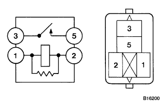 |
Remove the EFI relay from the engine room R/B.
Measure the EFI relay heater relay resistance.
| Tester Connections | Specified Conditions |
| 3 - 5 | 10 kΩ or higher |
| 3 - 5 | Below 1 Ω (when battery voltage applied to terminals 1 and 2 |
Reinstall the EFI relay.
|
| ||||
| OK | |
|
| 3.INSPECT ECM (HT1B OR HT2B VOLTAGE) |
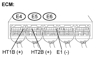 |
Turn the ignition switch on.
Measure the voltage between the terminals of the E4, E5 and E6 ECM connector.
| Tester Connections | Specified Conditions |
| HA1B (E4-1) - E1 (E6-1) | 9 to 14 V |
| HA2B (E5-5) - E1 (E6-1) | 9 to 14 V |
|
| ||||
| NG | |
|
| 4.CHECK HARNESS AND CONNECTOR (HEATED OXYGEN SENSOR - ECM, HEATED OXYGEN SENSOR - EFI RELAY) |
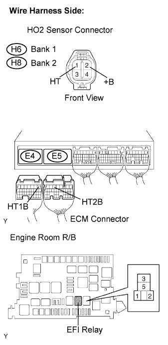 |
Check the harness and the connector between the ECM and the HO2 sensor.
Disconnect the H6 or H8 HO2 sensor connector.
Disconnect the E4 or E5 ECM connector.
Measure the resistance.
| Tester Connections | Specified Conditions |
| HT (H6-1) - HT1B (E4-1) | Below 1 Ω |
| HT (H8-1) - HT2B (E5-5) | Below 1 Ω |
| Tester Connections | Specified Conditions |
| HT (H6-1) or HT1B (E4-1) - Body ground | 10 kΩ or higher |
| HT (H8-1) or HT2B (E5-5) - Body ground | 10 kΩ or higher |
Check the harness and the connector between the HO2 sensor and EFI relay.
Inspect the EFI No. 2 fuse
Measure the resistance.
| Tester Connections | Specified Conditions |
| +B (H6-2) - EFI relay (3) | Below 1 Ω |
| +B (H8-2) - EFI relay (3) | Below 1 Ω |
| Tester Connections | Specified Conditions |
| +B (H6-2) or EFI relay (3) - Body ground | 10 kΩ or higher |
| +B (H8-2) or EFI relay (3) - Body ground | 10 kΩ or higher |
Reconnect the HO2 sensor connector.
Reconnect the ECM connector.
Reinstall the EFI relay.
|
| ||||
| OK | ||
 | ||
| ||
