Home › STEERING › POWER STEERING › POWER STEERING LINK

POWER STEERING LINK > INSTALLATION

for Preparation Click here


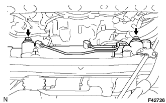
1. INSTALL POWER STEERING LINK ASSEMBLY


    F042726
  1. Install the power steering link assembly with the 2 bolts and 2 nuts.

    Torque:
    100 N*m{ 1,020 kgf*cm , 74 ft.*lbf }

    NOTICE:
    The nut has a detent, so never turn the nut, be sure to turn the bolt.

    HINT:
    Insert the bolt and slide it with the gear assembly as a unit and then install the bolt on the frame.


2. INSTALL STABILIZER BAR FRONT


3. STABILIZE SUSPENSION


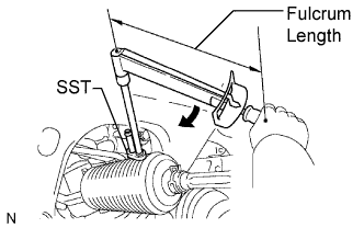
4. CONNECT STEERING GEAR OUTLET RETURN TUBE


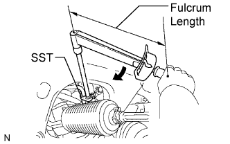
    F043639E01
  1. Using SST, connect the outlet return tube.

    SST
    09023-12701  

    Torque:
    42 N*m{ 428 kgf*cm , 31 ft.*lbf } for use with SST

    HINT:
    1. Use a torque wrench with a fulcrum length of 300 mm (11.81 in.).
    2. This torque value is effective in case that SST is parallel to a torque wrench.


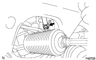
    F042723
  1. Install the hose with the clip.


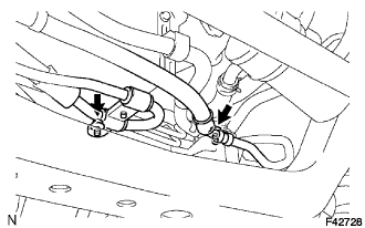
5. CONNECT PRESSURE FEED TUBE ASSEMBLY


    F042728
  1. Install the pressure feed tube assembly to the frame sub-assembly with the 2 bolts.

    Torque:
    28 N*m{ 286 kgf*cm , 21 ft.*lbf }


    F043638E01
  1. Using SST, tighten the flare nut and connect the pressure feed tube.

    SST
    09023-12701  

    Torque:
    42 N*m{ 428 kgf*cm , 31 ft.*lbf } for use with SST

    HINT:
    1. Use a torque wrench with a fulcrum length of 300 mmm (11.81 in.).
    2. This torque value is effective in case that SST is parallel to a torque wrench


6. TIGHTEN STEERING INTERMEDIATE SHAFT SUB-ASSEMBLY NO. 2


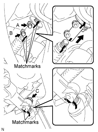
    F043317E02
  1. Align the matchmarks on the power steering gear and steering intermediate shaft sub-assembly No. 2.

  1. Install the steering intermediate shaft sub-assembly No. 2 to the steering gear box with the bolt C.

    Torque:
    Bolt C:
    36 N*m{ 360 kgf*cm , 27 ft.*lbf }


7. CONNECT TIE ROD END SUB-ASSEMBLY LH
  1. Connect the tie rod end to the steering knuckle arm.

  1. Install the nut and cotter pin.

    Torque:
    91 N*m{ 928 kgf*cm , 67 ft.*lbf }


8. CONNECT TIE ROD END SUB-ASSEMBLY RH

HINT:
Install the RH side by the same procedures with the LH side.


9. INSTALL ENGINE UNDER COVER SUB-ASSEMBLY NO. 1
  1. Install the engine under cover sub-assembly No. 1 with the 4 bolts.


10. INSTALL REAR ENGINE UNDER COVER ASSEMBLY
  1. Install the rear engine under cover assembly with the 6 bolts.


11. INSTALL FRONT WHEELS

Torque:
110 N*m{ 1,122 kgf*cm , 81 ft.*lbf }


12. PLACE FRONT WHEELS FACING STRAIGHT AHEAD


13. INSTALL TURN SIGNAL SWITCH ASSEMBLY


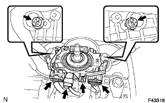
    F043318
  1. Install the turn signal switch assembly with the 3 screws.

  1. Connect the 3 connectors to the turn signal switch assembly.


14. INSTALL SPIRAL CABLE
  1. Check that the front wheels are facing straight ahead.

  1. Set the turn signal switch to the neutral position.

    NOTICE:
    If it is not in the neutral position, the pin of the turn signal switch may snap.


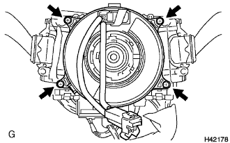
    H042178
  1. Install the spiral cable with the 4 screws.

    NOTICE:
    When replacing the spiral cable with a new one, remove the lock pin before installing the steering wheel assembly.

  1. Connect the connectors to the spiral cable.

    NOTICE:
    When handling the airbag connector, take care not to damage the airbag wire harness.


15. INSTALL STEERING COLUMN COVER LOWER
  1. Install the steering column cover lower to the steering column assembly.

  1. Install the 3 screws to the steering column cover upper and lower.


16. CENTER SPIRAL CABLE
  1. Check that the ignition switch is off.

  1. Check that the battery negative (-) terminal is disconnected.

    CAUTION:
    After removing the terminal, wait for at least 90 seconds before starting the operation.


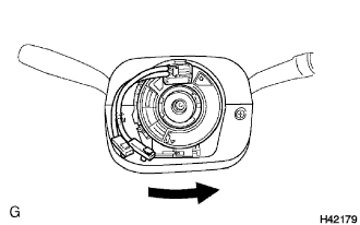
    H042179
  1. Rotate the spiral cable counterclockwise slowly by hand until it feels firm.

    NOTICE:
    Do not turn the spiral cable by the airbag wire harness.


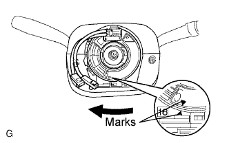
    H042180E02
  1. Rotate the spiral cable clockwise approximately 2.5 turns to align the marks.

    NOTICE:
    Do not turn the spiral cable by the airbag wire harness.

    HINT:
    The spiral cable will rotate approximately 2.5 turns to both the left and right from the center.


17. INSTALL STEERING WHEEL ASSEMBLY
  1. Align the matchmarks on the steering wheel and main shaft assembly.

  1. Install the steering set nut.

    Torque:
    50 N*m{ 510 kgf*cm , 37 ft.*lbf }

  1. without Steering pad switch:
    Connect the connector.


18. INSPECT STEERING WHEEL CENTER POINT

HINT:
This is the adjustment procedure for steering off center.


  1. Inspect steering wheel off center.


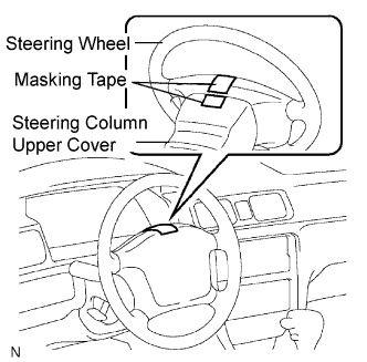
      F016015E08
    1. Apply masking tape on the top center of the steering wheel and steering column upper cover.

    2. Drive the vehicle in a straight line for 100 meters at a constant speed of 35 mph (56 km/h), and hold the steering wheel to maintain the course.


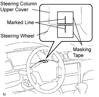
    3. F016016E10
    4. Draw a line on the masking tape as shown in the illustration.

    5. Turn the steering wheel to the center position.

      HINT:
      Look at the upper surface of the steering wheel, steering spoke and SRS airbag line to find the center position.


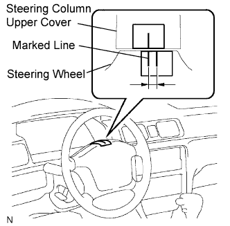
    6. F016017E07
    7. Draw a new line on the masking tape on the steering wheel as shown in the illustration.

    8. Measure the distance between the 2 lines on the masking tape on the steering wheel.

    9. Convert the measured distance to steering angle.

      HINT:
      1. Measured distance 1 mm (0.04 in.) = Steering angle of approximately 1 degree.
      2. Make a note of the steering angle.


  1. Adjust steering angle.


      R000429E09
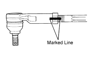
    1. Draw a line on the RH and LH tie rod ends and rack ends respectively where it can be easily seen.

    2. Using a paper gauge, measure the distance from the RH and LH tie rod ends to the rack end screws.

      HINT:
      1. Measure both the RH and LH sides.
      2. Make a note of the measured values.


    3. F016018E04
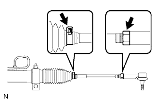
    4. Remove the RH and LH boot clips from the rack boots.

    5. Loosen the RH and LH lock nuts.

    6. Turn the RH and LH rack ends by the same amount (but in different directions) according to the steering angle.
      HINT:
      One 360 degree turn of rack end (1.5 mm (0.059 in.) horizontal movement) equals to 12 degrees of steering angle.

    7. Tighten the RH and LH lock nuts to the specified torque.

      Torque:
      56 N*m{ 570 kgf*cm , 41 ft.*lbf }

      NOTICE:
      Make sure that the difference in length between the RH and LH tie rod ends and rack end screws is within 1.5 mm (0.059 in.).

    8. Install the RH and LH boot clips.


19. INSTALL STEERING PAD


    H042354
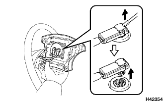
  1. Support the steering pad with one hand as shown in the illustration.

  1. Connect the 2 connectors to the steering pad.

    NOTICE:
    When handling the airbag connector, take care not to damage the airbag wire harness.

  1. Connect the horn connector.

  1. Confirm that the circumference groove of the "torx" screw fits in the screw case, and place the steering pad onto the steering wheel assembly.

  1. Using a "torx" socket wrench (T30), tighten the 2 "torx" screws.

    Torque:
    8.8 N*m{ 90 kgf*cm , 78 in.*lbf }


20. INSPECT STEERING PAD


    H042163
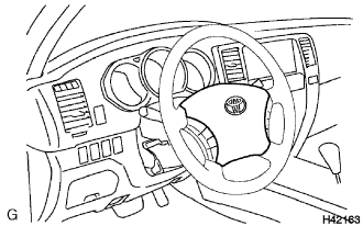
  1. With the steering pad installed on the vehicle, perform a visual check. If there are any defects as mentioned below, replace the steering pad with a new one:

    1. Cuts, minute cracks or marked discoloration on the steering pad top surface or in the grooved portion.

  1. Make sure that the horn sounds.

    HINT:
    If the horn does not sound, inspect the horn system (Click here).


21. INSPECT SRS WARNING LIGHT
  1. Inspect the SRS warning light (Click here).


22. ADD POWER STEERING FLUID


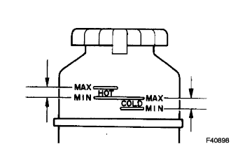
    F040898
  1. Keep the vehicle horizontal.

  1. With the engine stopped, check the fluid level in the reservoir.
    If necessary, add fluid.

    Fluid:
    ATF DEXRON II or III

    HINT:
    If the fluid is hot, check that the fluid level is within the HOT range. If the fluid is cold, check that the fluid level is within the COLD range.

  1. Start the engine and run at idle.

  1. Turn the steering wheel from lock to lock several times to raise fluid temperature.

    Fluid temperature:
    75 to 80°C (167 to 176°F)


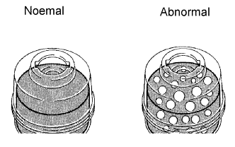
    F040897E07
  1. Check for foaming or emulsification.
    If foaming or emulsification is identified, bleed the power steering system.


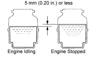
    R011786E08
  1. With the engine idling, measure the fluid level in the reservoir.

  1. Stop the engine.

  1. Wait a few minutes and remeasure the fluid level in the reservoir.

    Maximum fluid level rise:
    About 5 mm (0.20 in.)

    If a problem is found, bleed the power steering system.

  1. Check the fluid level.


23. BLEED POWER STEERING FLUID
  1. Check the fluid level.

  1. Jack up the front of the vehicle and support it with stands.

  1. Turn the steering wheel.

    1. With the engine stopped, turn the wheel slowly from lock to lock several times.

  1. Lower the vehicle.

  1. Start the engine.

    1. Run the engine at idle for a few minutes.

  1. Turn the steering wheel.

    1. With the engine idling, turn the wheel left or right to the full lock position and keep it there for 2 to 3 seconds, then turn the wheel to the opposite full lock position and keep it there for 2 to 3 seconds.*1

    2. Repeat (*1) several times.

  1. Stop the engine.


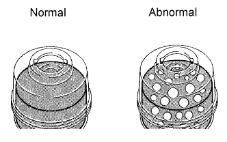
    F040897E06
  1. Check for foaming or emulsification.
    Especially, if the system has to be held twice because of foaming or emulsification, check for fluid leaks in the system.

  1. Check the fluid level.


24. CHECK POWER STEERING FLUID LEAKAGE
  1. Check the fluid level.

  1. Jack up the front of the vehicle and support it with stands.

  1. Turn the steering wheel.

    1. With the engine stopped, turn the wheel slowly from lock to lock several times.

  1. Lower the vehicle.

  1. Start the engine.

    1. Run the engine at idle for a few minutes.

  1. Turn the steering wheel.

    1. With the engine idling, turn the wheel left or right to the full lock position and keep it there for 2 to 3 seconds, then turn the wheel to the opposite full lock position and keep it there for 2 to 3 seconds.*1

    2. Repeat (*1) several times.

  1. Stop the engine.


    F040897E06
  1. Check for foaming or emulsification.
    Especially, if the system has to be held twice because of foaming or emulsification, check for fluid leaks in the system.

  1. Check the fluid level.


25. INSPECT AND ADJUST FRONT WHEEL ALIGNMENT

HINT:
Click here.