 |
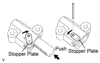
While turning the stopper plate of the tensioner clockwise, push in the plunger of the tensioner as shown in the illustration.
TIMING CHAIN > INSTALLATION |
| 1. INSTALL CHAIN TENSIONER SLIPPER |
| 2. INSTALL NO. 1 CHAIN TENSIONER ASSEMBLY |
|
While turning the stopper plate of the tensioner clockwise, push in the plunger of the tensioner as shown in the illustration.
While turning the stopper plate of the tensioner counterclockwise, insert a bar of φ3.5 mm (0.138 in.) into the holes on the stopper plate and tensioner to fix the stopper plate.
Install the chain tensioner with the 2 bolts.
| 3. INSTALL CHAIN SUB-ASSEMBLY |
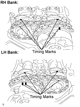 |
Set the No. 1 cylinder to the TDC / compression.
Align the timing marks of the camshaft timing gears and bearing caps.
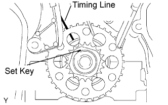 |
Install the crankshaft pulley set bolt, and turn the crankshaft to align the crankshaft set key with the timing line of the cylinder block.
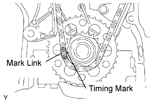 |
Align the mark link (yellow) with the timing mark of the crankshaft timing gear.
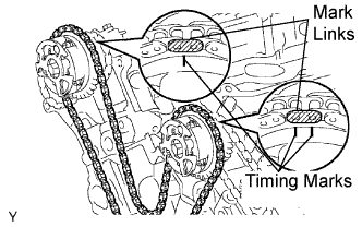 |
Align the mark links (orange) with the timing marks of the camshaft timing gears, and install the chain.
| 4. INSTALL NO. 2 CHAIN VIBRATION DAMPER |
Instal the 2 No. 2 chain vibration dampers.
| 5. INSTALL NO. 1 IDLE GEAR SHAFT |
Apply a light coat of engine oil to the rotating surface of the No. 1 idle gear shaft.
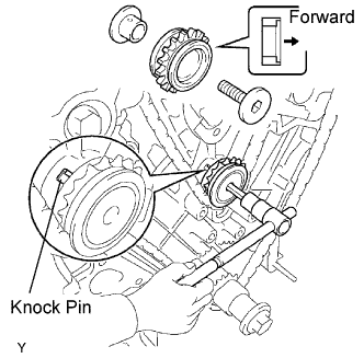 |
Temporarily install the No. 1 idle gear shaft and No. 1 idle gear with the No. 2 idle gear shaft while aligning the knock pin of the No. 1 idle gear shaft with the knock pin groove of the cylinder block.
Using a 10 mm hexagon wrench, tighten the No. 2 idle gear shaft.
Remove the bar from the chain tensioner.
| 6. INSTALL TIMING GEAR CASE OR TIMING CHAIN CASE OIL SEAL |
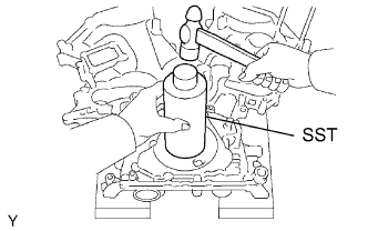 |
Using SST and a hammer, tap in a new oil seal until its surface is flush with the timing chain cover edge.
Apply MP grease to the oil seal lip.
| 7. INSTALL TIMING CHAIN OR BELT COVER SUB-ASSEMBLY |
Remove any old packing (FIPG) material and be careful not to drop any oil on the contact surfaces of the timing chain cover, cylinder head and cylinder block.
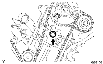 |
Install a new O-ring to the LH cylinder head as shown in the illustration.
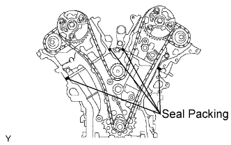 |
Apply a continuous bead of seal packing (diameter 3.0 to 4.0 mm (0.12 to 0.16 in.)) to 4 locations as shown in the illustration.
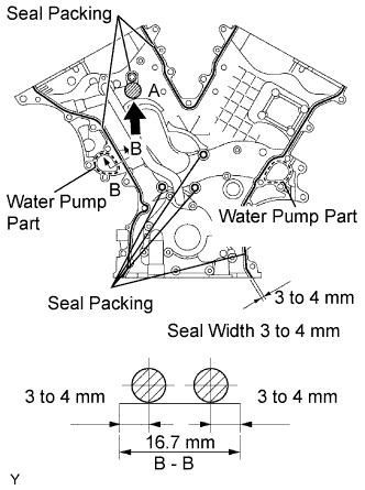 |
Apply a continuous bead of seal packing (diameter 3.0 to 4.0 mm (0.12 to 0.16 in.)) to the timing chain cover as shown in the illustration.
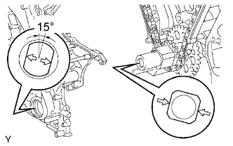 |
Align the key way of the oil pump drive rotor with the rectangular portion of the crankshaft timing gear, and slide the timing chain cover into place.
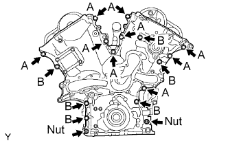 |
Install the timing chain cover with the 15 bolts and 2 nuts. Tighten the bolts and nuts uniformly in several steps.
| 8. INSTALL VVT SENSOR |
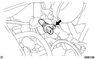 |
LH bank side VVT sensor.
Apply a light coat of engine oil to an O-ring of the VVT sensor.
Install the VVT sensor with the bolt.
Connect the VVT sensor connector.
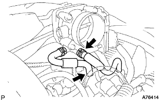 |
Connect the water by-pass hoses No. 4 and No. 5.
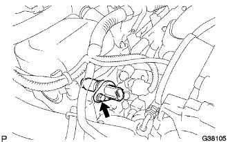 |
RH bank side VVT sensor.
Apply a light coat of engine oil to an O-ring of the VVT sensor.
Install the VVT sensor with the bolt.
Connect the VVT sensor connector.
| 9. INSTALL CAMSHAFT TIMING OIL CONTROL VALVE ASSEMBLY |
Insert the camshaft timing oil control valves to each cylinder head, and tighten the 2 bolts.
| 10. INSTALL CYLINDER HEAD COVER SUB-ASSEMBLY LH |
Remove any old packing (FIPG) material and be careful not to drop any oil on the contact surfaces of the cylinder head, timing chain cover and cylinder head cover.
Apply adhesive to the threads of the ventilation valve.
Install the ventilation valve to the cylinder head cover.
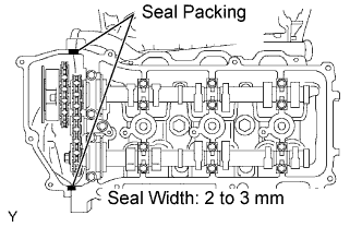 |
Apply a continuous bead of seal packing (diameter: 2 to 3 mm (0.08 to 0.12 in.)) to the cylinder head and timing chain cover as shown in the illustration.
Install the gasket to the cylinder head cover.
Install the seal washers to the bolts.
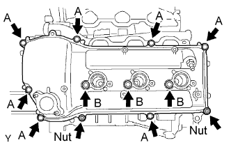 |
Install the cylinder head cover with the 10 bolts and 2 nuts. Tighten the bolts and nuts uniformly in several steps.
| 11. INSTALL CYLINDER HEAD COVER SUB-ASSEMBLY |
Remove any old packing (FIPG) material and be careful not to drop any oil on the contact surfaces of the cylinder head, timing chain cover and cylinder head cover.
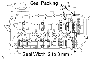 |
Apply a continuous bead of seal packing (diameter: 2 to 3 mm (0.08 to 0.12 in.)) to the cylinder head and timing chain cover as shown in the illustration.
Install the gasket to the cylinder head cover.
Install the seal washers to the bolts.
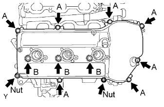 |
Install the cylinder head cover with the 10 bolts and 2 nuts. Tighten the bolts and nuts uniformly in several steps.
| 12. INSTALL IGNITION COIL ASSEMBLY |
| 13. INSTALL INTAKE AIR SURGE TANK |
Install a new gasket to the intake air surge tank.
Using the socket hexagon wrench 8, install the intake air surge tank with the 4 bolts.
Install the 2 intake air surge tank nuts.
Install the 2 surge tank stays with the 4 bolts.
Install the oil baffle plate with the bolt.
Install the throttle body bracket with the 2 bolts.
Install the 3 wire harness clamps and hose clamp.
Connect the throttle body with motor connector.
Connect the 2 VSV connectors.
Connect the ventilation hose.
Connect the fuel vapor feed hose.
Connect the 2 water by-pass hoses.
| 14. INSTALL OIL PAN SUB-ASSEMBLY |
Remove any old packing (FIPG) material and be careful not to drop any oil on the contact surfaces of the cylinder block, rear oil seal retainer and oil pan.
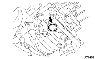 |
Install a new O-ring to the oil pump.
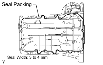 |
Apply a continuous bead of seal packing (diameter: 3 to 4 mm (0.12 to 0.16 in.)) to the oil pan as shown in the illustration.
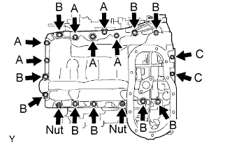 |
Install the oil pan with the 17 bolts and 2 nuts. Tighten the bolts and nuts uniformly in several steps.
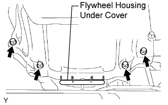 |
Install the 4 housing bolts.
Install the flywheel housing under cover.
| 15. INSTALL OIL STRAINER SUB-ASSEMBLY |
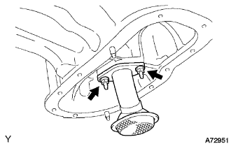 |
Install a new gasket and the oil strainer with the 2 nuts.
| 16. INSTALL NO. 2 OIL PAN SUB-ASSEMBLY |
Remove any old packing (FIPG) material and be careful not to drop any oil on the contact surfaces of the oil pan and No. 2 oil pan.
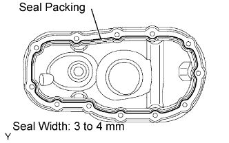 |
Apply a continuous bead of seal packing (diameter 3: to 4 mm (0.12 to 0.16 in.)) as shown in the illustration.
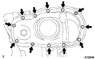 |
Install the No. 2 oil pan with the 10 bolts and 2 nuts. Tighten the bolts and nuts uniformly in several steps.
| 17. INSTALL CRANKSHAFT PULLEY |
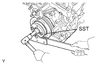 |
Using SST, install the pulley set bolt.
| 18. INSTALL NO. 1 IDLER PULLEY SUB-ASSEMBLY |
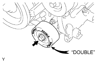 |
Install the idler pulley with the bolt.
| 19. INSTALL NO. 2 IDLER PULLEY SUB-ASSEMBLY |
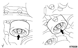 |
Install the 2 idler pulleys with the 2 bolts.
| 20. INSTALL V-RIBBED BELT TENSIONER ASSEMBLY |
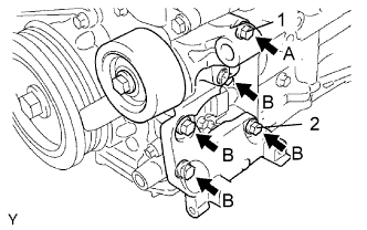 |
Temporarily install the V-ribbed belt tensioner with the 5 bolts.
Install the V-ribbed belt tensioner by tightening the bolt 1 and bolt 2 in the order shown in the illustration.
Tighten the other bolts.
| 21. INSTALL COOLER COMPRESSOR ASSEMBLY |
Install the cooler compressor assembly with the 4 bolts.
Connect the cooler compressor assembly connector.
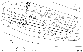 |
Install the suction hose sub-assembly with the bolt.
| 22. INSTALL GENERATOR ASSEMBLY |
Install the generator assembly with the 2 bolts.
Install the wire harness clamp bracket with the 2 bolts.
Connect the wire harness.
Connect the wire harness to the terminal B and install the nut.
Connect the connector to the generator assembly.
Install the wire harness stay with the bolt.
| 23. INSTALL VANE PUMP ASSEMBLY |
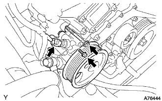 |
Install the vane pump with the 2 bolts.
Connect the P/S oil pressure switch connector.
| 24. INSTALL WATER INLET |
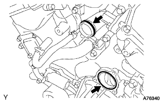 |
Install a new O-ring to the water outlet pipe.
Install a new gasket to the water pump.
Apply soapy water to the O-ring.
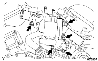 |
Install the water inlet with the 5 bolts.
Connect the 5 water by-pass hoses.
Connect the 2 radiator hoses.
Connect the 2 oil cooler hoses (with oil cooler).
| 25. INSTALL OIL LEVEL GAUGE GUIDE |
Install a new O-ring to the oil level gauge guide.
Apply a light coat of engine oil to the O-ring.
Push in the oil level gauge guide end into the guide hole of the oil pan.
Install the oil level gauge guide with the bolt.
Install the oil level gauge.
| 26. INSTALL AIR CLEANER ASSEMBLY |
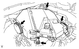 |
Install the air cleaner with the 2 bolts.
Tighten the 2 hose clamps.
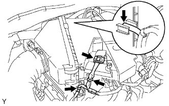 |
Install the 2 wire harness clamps.
Connect the mass air flow meter connector.
Connect the vacuum hose.
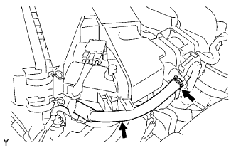 |
Connect the ventilation hose No. 2.
| 27. CONNECT NO. 2 VENTILATION HOSE |
| 28. INSTALL FLUID COUPLING ASSEMBLY |
Put the fan pulley to the water pump.
Put the fan with fluid coupling and fan shroud together.
Temporarily install the 4 fluid coupling nuts.
Tighten the 2 fan shroud bolts and radiator reserve tank bolt.
Connect the reserve tank hose.
Fasten the 2 oil cooler hoses with the hose clamp.
| 29. INSTALL FAN AND GENERATOR V BELT |
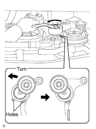 |
While turning the belt tensioner counterclockwise, align with its holes, and then insert a bar of 6 mm (0.24 in.) into the holes to fix the belt tensioner.
Install the V-ribbed belt.
While turning the belt tensioner counterclockwise, remove the bar.
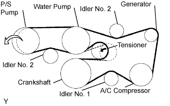 |
If it is hard to install the V-ribbed belt, perform the following procedure.
Put the V-ribbed belt on all parts except the P/S pump, as shown in the illustration.
While releasing the belt tension by turning the belt tensioner counterclockwise, put the V-ribbed belt on the P/S pump.
| 30. FULLY TIGHTEN FLUID COUPLING ASSEMBLY |
Tighten the 4 fluid coupling bolts.
| 31. INSTALL RADIATOR SUPPORT SEAL UPPER |
| 32. INSTALL BATTERY |
| 33. INSTALL DIFFERENTIAL CARRIER ASSEMBLY FRONT |
| 34. INSTALL POWER STEERING LINK ASSEMBLY |
| 35. ADD ENGINE OIL |
Fill with fresh engine oil.
| Drain and refill with oil filter change | 5.2 liters (5.5 US qts, 4.6 lmp. qts) |
| Drain and refill without oil filter change | 4.9 liters (5.2 US qts, 4.3 lmp. qts) |
| Dry fill | 6.0 liters (6.3 US qts, 5.3lmp. qts) |
Reinstall the oil filler cap.
| 36. ADD ENGINE COOLANT |
Slowly fill the system with engine coolant.
Install the radiator cap securely.
Bleed the cooling system.
Open the heater water valve while warming up the engine.
Maintain the engine speed at 2,000 to 2,500 rpm and warm up the engine.
Stop the engine and wait until the coolant cools down.
Add coolant into the reservoir until the coolant level is FULL.
| 37. CHECK FOR ENGINE OIL LEAKS |
| 38. CHECK FOR ENGINE COOLANT LEAKS |
Fill the radiator with coolant and attach a radiator cap tester.
Pump it to 118 kPa (1.2 kgf/cm2 17.1 psi), then check for leakage.
| 39. INSTALL V-BANK COVER |
Install the V-bank cover with the 2 nuts.
| 40. INSPECT IGNITION TIMING |
Warm up the engine.
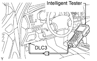 |
When using the intelligent tester.
Connect the intelligent tester to the DLC3.
Select the following menu items: DIAGNOSIS / ENHANCED OBD ll / DATA LIST / IGN ADVANCE.
Inspect the ignition timing during idling.
Check that the ignition timing advances immediately when the engine speed is increased.
 |
When not using intelligent tester.
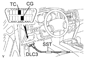
Using SST, connect the terminals 13 (TC) and 4 (CG) of the DLC3.
Remove the air cleaner cap sub-assembly.
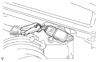 |
Pull out the wire harness as shown in the illustration.
Connect the tester probe of a timing light to the wire of the ignition coil connector for No. 1 cylinder.
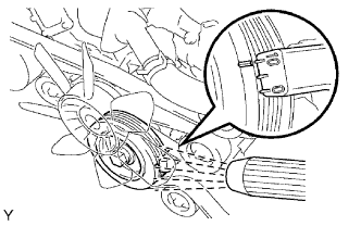 |
Inspect the ignition timing during idling.
Remove the SST from the DLC3.
Inspect the ignition timing during idling.
Disconnect the timing light from the engine.
Install the air cleaner cap sub-assembly.