 |
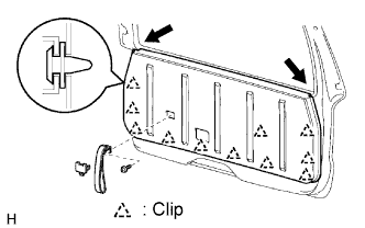
Remove the assist strap hole cover.
BACK DOOR > DISASSEMBLY |
| 1. REMOVE BACK DOOR TRIM BOARD |
|
Remove the assist strap hole cover.
Remove the screw and assist strap.
Using a screwdriver, remove the back door trim cover.
Using a clip remover, remove the 10 clips and trim board.
Remove the inner weatherstrip.
| 2. REMOVE BACK DOOR SERVICE HOLE COVER LH |
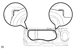 |
Remove the back door service hole cover LH.
| 3. REMOVE BACK DOOR GLASS |
Remove the 5 screws and service hole cover.
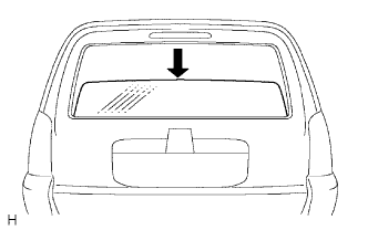 |
Open the door glass until the bolts appear in the service hole.
Remove the door glass run.
Disconnect the window defogger connector.
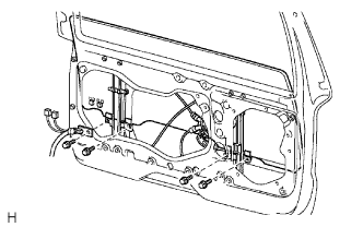 |
Remove the 4 bolts and door glass.
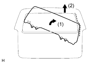 |
Remove the door glass as shown in the illustration.
Disconnect the rear window connector.
Remove the multiplex network door ECU.
| 4. REMOVE BACK DOOR GLASS WEATHERSTRIP ASSEMBLY OUTER |
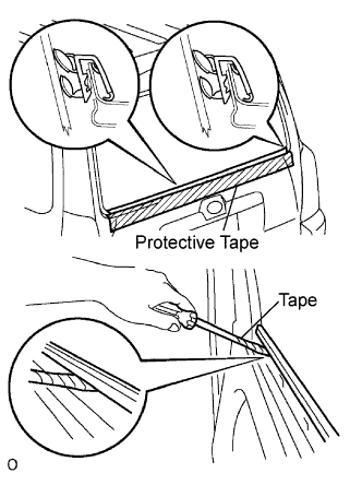 |
Put protective tape under the glass weatherstrip.
Using a screwdriver or moulding remover, disengage the claw and remove the glass weatherstrip outer.
| 5. REMOVE WITH MOTOR BACK DOOR LOCK ASSEMBLY |
Disconnect the back door lock connector.
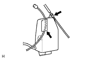 |
Remove the 2 back window regulator control wires.
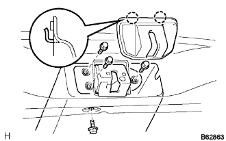 |
Disengage the 2 claws and remove the lock protector as shown in the illustration.
Remove the 4 bolts and back door lock.
| 6. REMOVE BACK DOOR POWER WINDOW REGULATOR SUB-ASSEMBLY |
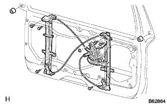 |
Remove the 2 cushion rubbers.
Disconnect the window regulator connector.
Remove the 6 bolts, nut and window regulator.
| 7. REMOVE POWER WINDOW REGULATOR MOTOR ASSEMBLY LH REAR |
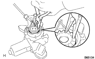 |
Remove the 2 nuts and window regulator motor.
Remove the 2 screws and cover plate.
Using needle nose pliers, remove the drum and wire guide from the motor.
| 8. REMOVE REAR WIPER MOTOR ASSEMBLY |
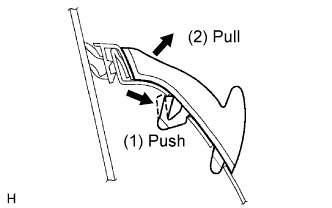 |
Remove the liner wiper step LH as shown in the illustration.
Remove the rear wiper motor assembly (Click here).
| 9. REMOVE BACK DOOR LOCK CYLINDER |
Disconnect the connector.
Remove the tailgate control switch.
Remove the 2 nuts and lock cylinder.
| 10. REMOVE BACK DOOR GARNISH SUB-ASSEMBLY OUTSIDE |
Remove the assist strap hole cover.
Remove the assist strap assembly RH.
Remove the back door trim panel.
Remove the service hole cover LH.
| 11. REMOVE TELEVISION CAMERA ASSEMBLY (w/ Rear View Monitor System) |
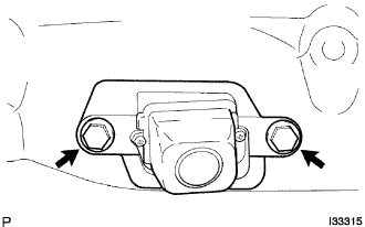 |
Disconnect the connector and remove the connector clamp.
Remove the 2 screws and the television camera assembly.
| 12. REMOVE BACK DOOR STOPPER LOWER |
Remove the bolt and stopper lower.
| 13. REMOVE BACK DOOR LOWER STOPPER CUSHION |
Remove the 2 bolts and stopper cushion.
| 14. REMOVE REAR SPOILER SUB-ASSEMBLY (w/ Rear Spoiler) |
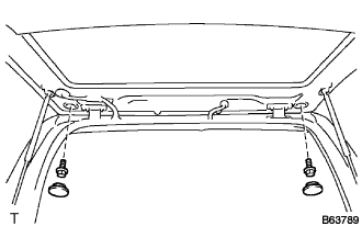 |
Remove the 2 grommets, 2 bolts and spoiler.
Disconnect the center stop light connector.
| 15. REMOVE CENTER STOP LIGHT ASSEMBLY (w/ Rear Spoiler) |
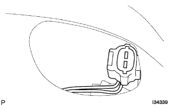 |
Disconnect the connector.
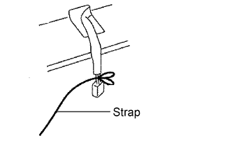 |
Install the strap on the connector of center stop light assembly.
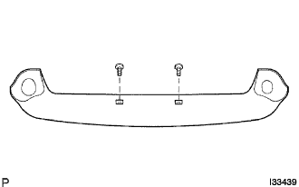 |
Remove the 2 screws.
Pass the connector through the inside the rear spoiler sub-assembly and remove the center stop light assembly with bracket.
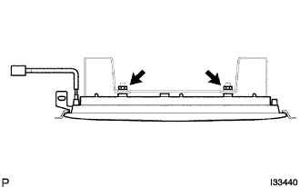 |
Remove the 2 nuts and center stop light assembly.
| 16. REMOVE CENTER STOP LIGHT ASSEMBLY (w/o Rear Spoiler) |
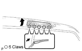 |
Release the 5 fitting claws as shown in the illustration.
Disconnect the connector and remove the center stop light assembly.