 |
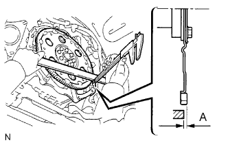
Using calipers and a straight edge, measure dimension A between the engine and the end surface of the drive plate.
AUTOMATIC TRANSMISSION ASSEMBLY (for 2UZ-FE) > INSTALLATION |
| 1. INSTALL TORQUE CONVERTER CLUTCH ASSEMBLY |
Install the torque converter clutch to the automatic transmission.
|
Using calipers and a straight edge, measure dimension A between the engine and the end surface of the drive plate.
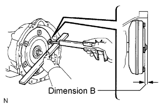 |
Using calipers and a straight edge, measure the dimension B shown in the illustration and check that B is greater than A measured in (b).
| 2. INSTALL NO.1 REAR ENGINE MOUNTING INSULATOR |
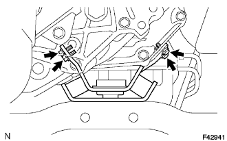 |
Install the engine mounting insulator rear and 4 bolts to the automatic transmission.
| 3. INSTALL TRANSFER ASSEMBLY |
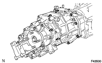 |
Install the transfer assembly with the 8 bolts.
| 4. INSTALL AUTOMATIC TRANSMISSION ASSEMBLY |
| 5. INSTALL FLYWHEEL HOUSING UNDER COVER |
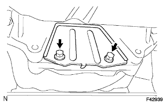 |
Install the flywheel housing under cover and 2 bolts.
| 6. INSTALL WIRE HARNESS |
| 7. INSTALL NO.3 FRAME CROSSMEMBER SUB-ASSEMBLY |
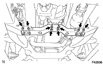 |
Install the No. 3 frame crossmember sub-assembly with 4 bolts and 4 nuts.
Install the No. 3 frame crossmember sub-assembly with 4 bolts.
| 8. INSTALL NO.1 TRANSMISSION CONTROL CABLE BRACKET |
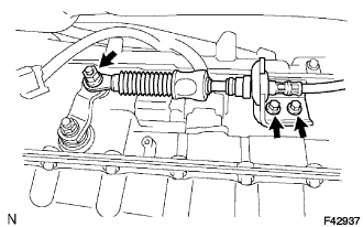 |
Install the No. 1 transmission control cable bracket with 2 bolts.
| 9. CONNECT TRANSMISSION CONTROL CABLE ASSEMBLY |
Connect the transmission control cable with nut.
| 10. INSTALL NO.1 OIL COOLER OUTLET TUBE |
Temporarily install the No. 1 oil cooler outlet tube.
Temporarily install the No. 1 oil cooler inlet tube.
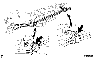 |
Install the 2 clamps and 2 bolts.
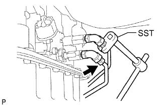 |
Using SST, tighten the No. 1 oil cooler outlet tube.
| 11. INSTALL NO.1 OIL COOLER INLET TUBE |
Using SST, tighten the No. 1 oil cooler inlet tube.
| 12. INSTALL TRANSMISSION OIL FILLER TUBE SUB-ASSEMBLY |
Coat a new O-ring with ATF, and install them to the oil filler tube.
Install the oil filler tube and bolt to the automatic transmission.
Install the ATF level gauge.
| 13. INSTALL FRONT SUSPENSION MEMBER BRACKET LH |
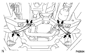 |
Install the front suspension member bracket LH with 4 bolts.
| 14. INSTALL FRONT SUSPENSION MEMBER BRACKET |
Install the front suspension member bracket with 4 bolts.
| 15. INSTALL PROPELLER SHAFT ASSEMBLY |
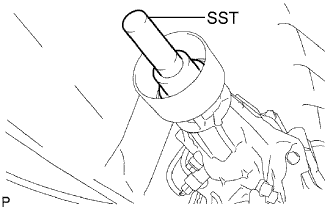 |
Remove the SST from the extension housing.
Install the propeller shaft assembly in the extension housing.
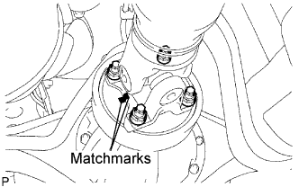 |
Align the matchmarks on the propeller shaft flange and differential flange.
Install the propeller shaft assembly with the 4 nuts and 4 washers.
| 16. INSTALL FRONT PROPELLER SHAFT ASSEMBLY |
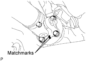 |
Align the matchmarks on the yoke and differential flange.
Install the propeller shaft assembly with the 4 bolts, 4 nuts and 4 washers.
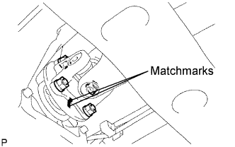 |
Align the matchmarks on the yoke and transfer flange.
Install the propeller shaft assembly with the 4 nuts and 4 washers.
| 17. ADJUST SHIFT LEVER POSITION |
| 18. INSTALL EXHAUST PIPE |
| 19. INSTALL OXYGEN SENSOR |
| 20. INSTALL NO.1 ENGINE UNDER COVER SUB-ASSEMBLY |
| 21. INSTALL REAR ENGINE UNDER COVER ASSEMBLY |
| 22. ADD AUTOMATIC TRANSMISSION FLUID |
| 23. ADJUST AUTOMATIC TRANSMISSION FLUID |
| 24. INSPECT SHIFT LEVER POSITION |
| 25. CHECK FOR EXHAUST GAS LEAKS |
| 26. RESET MEMORY |