 |
CYLINDER HEAD > REMOVAL |
| 1. DISCHARGE FUEL SYSTEM PRESSURE |
| 2. REMOVE TIMING BELT |
| 3. REMOVE CAMSHAFT (for RH Side) |
|
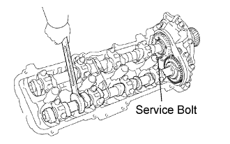 |
Bring the service bolt hole of the sub-gear upward by turning the hexagonal portion of the exhaust camshaft with a wrench.
Secure the sub-gear to the main gear with a service bolt.
| Thread diameter | 6 mm |
| Thread pitch | 1.0 mm |
| Bolt length | 16 to 20 mm |
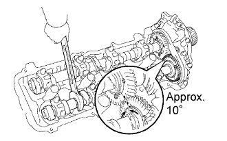 |
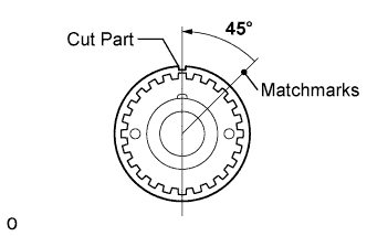
Set the timing mark (1-dot mark) of the camshaft main gear at approx. 10° angle by turning the hexagonal portion of the exhaust camshaft with a wrench.
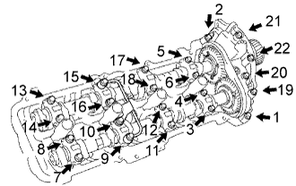 |
Uniformly loosen and remove the 22 bearing cap bolts in several steps, in the order shown in the illustration.
Remove the oil feed pipe, 9 bearing caps, camshaft housing plug, oil control valve filter, and camshafts.
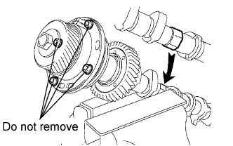 |
Mount the hexagonal portion of the camshaft in a vise.
Remove the screw plug and seal washer.
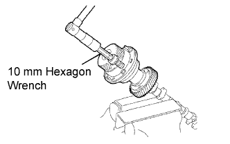 |
Using a 10 mm hexagon wrench, remove the bolt.
Pull out the timing tube and drive gear from the camshaft.
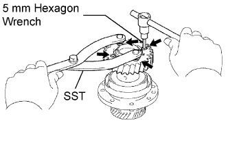 |
Using SST and a 5 mm hexagon wrench, remove the 4 bolts, drive gear and oil seal.
| 4. REMOVE CAMSHAFT (for LH Side) |
| 5. REMOVE TRANSMISSION OIL FILLER TUBE SUB-ASSEMBLY |
Remove the bolt and transmission oil filler tube.
| 6. REMOVE OIL LEVEL GAGE GUIDE |
Remove the bolt and oil level gauge guide.
| 7. REMOVE INTAKE MANIFOLD ASSEMBLY |
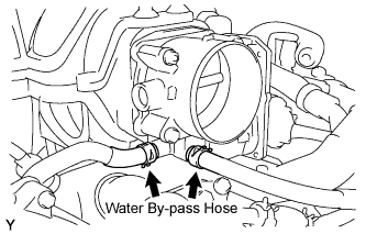 |
Disconnect the 2 water by-pass hoses from the throttle body.
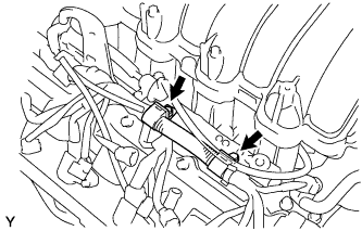 |
Disconnect the 2 wire clamps from the wire clamp bracket on the RH delivery pipe.
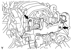 |
Remove the bolt and nut holding the engine wire protector from the intake manifold and cylinder head.
Remove the 2 bolts and ground cables from the RH and LH cylinder heads.
Remove the bolt and V-bank cover bracket from the intake manifold.
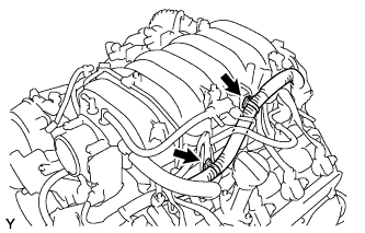 |
Disconnect the engine wire from the engine hanger and wire bracket.
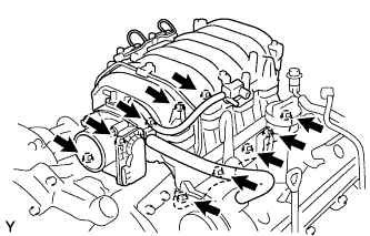 |
Remove the bolt and wire bracket from the intake manifold.
Remove the 6 bolts, 4 nuts, intake manifold assembly and 2 gaskets.
| 8. REMOVE WATER INLET HOUSING |
Remove the 2 bolts.
Remove the water inlet housing and O-ring from the engine.
| 9. REMOVE WATER BY-PASS JOINT FR |
Remove the 4 nuts.
Remove the water by-pass joint and 2 gaskets.
| 10. REMOVE WATER BY-PASS PIPE SUB-ASSEMBLY |
Remove the bolt and water by-pass pipe.
| 11. REMOVE NO. 2 AIR SWITCHING VALVE |
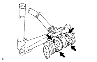 |
Remove the 2 vacuum hoses from the No. 2 air switching valves.
Remove the 4 bolts, 2 gaskets and the 2 No. 2 air switching valves from the water by-pass joint rear.
| 12. REMOVE WATER BY-PASS JOINT RR |
Remove the 4 nuts, water by-pass joint and 2 gaskets.
| 13. REMOVE ENGINE WIRE |
| 14. REMOVE NO. 2 REAR TIMING BELT PLATE RH |
Remove the 2 bolts and No. 2 rear timing belt plate RH.
| 15. REMOVE REAR TIMING BELT PLATE RH |
Remove the bolt, stud bolt and rear timing plate RH.
| 16. REMOVE NO. 2 REAR TIMING BELT PLATE LH |
Remove the 2 bolts and No. 2 rear timing belt plate LH.
| 17. REMOVE REAR TIMING BELT PLATE LH |
Remove the bolt and rear timing belt plate LH.
| 18. REMOVE FRONT EXHAUST PIPE |
Remove the 2 bolts and separate the front exhaust pipe.
| 19. REMOVE CYLINDER HEAD SUB-ASSEMBLY |
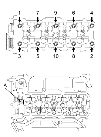 |
Uniformly loosen the 10 cylinder head bolts in the order shown in the illustration. Remove the bolts and plate washers.
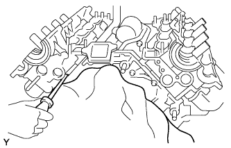 |
Remove the cylinder head from the dowels on the cylinder block, and place the cylinder head on wooden blocks on a bench.
| 20. REMOVE CYLINDER HEAD SUB-ASSEMBLY LH |
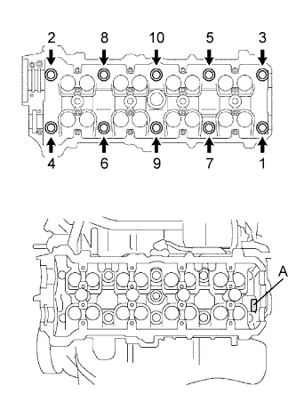 |
Uniformly loosen the 10 cylinder head bolts in the order shown in the illustration. Remove the bolts and plate washers.
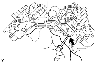 |
Lift the cylinder head from the dowels on the cylinder block, and place the cylinder head on wooden blocks on a bench.
| 21. REMOVE CYLINDER HEAD GASKET |
| 22. REMOVE NO. 2 CYLINDER HEAD GASKET |